SLLU345 May 2022 ISOUSB111
6 PCB Layout and 3D Diagram
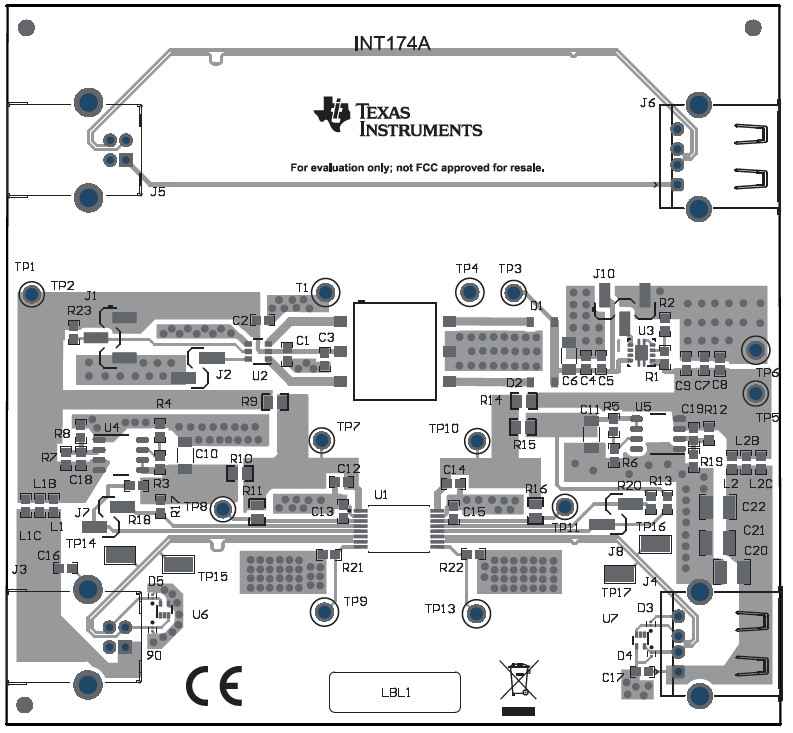
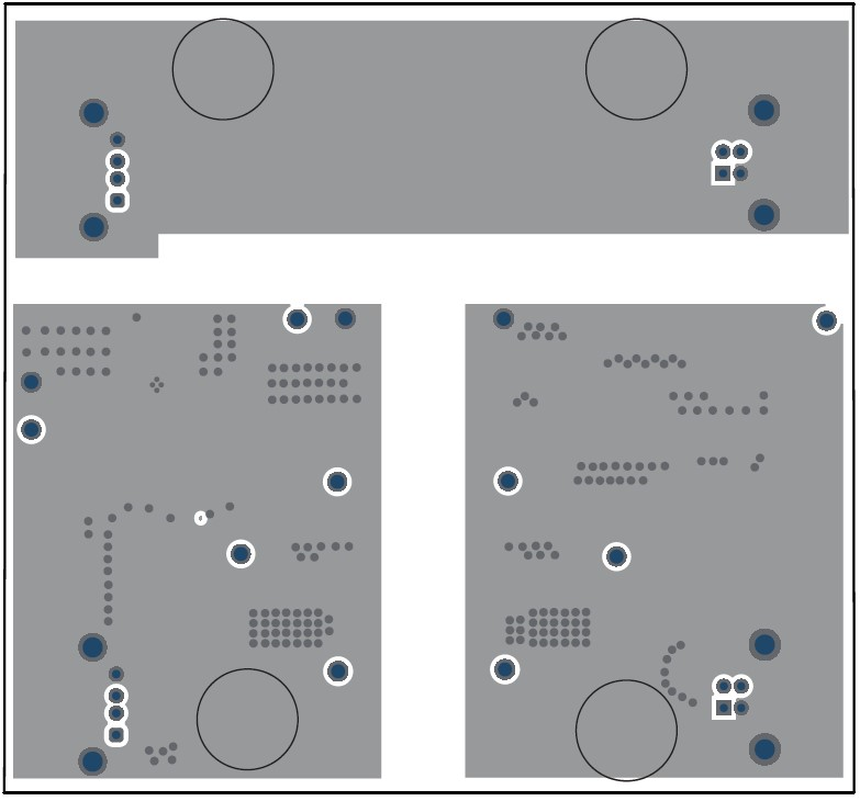
ISOUSB111DWXEVM PCB Layout - Top Layerand Figure 6-2 show the
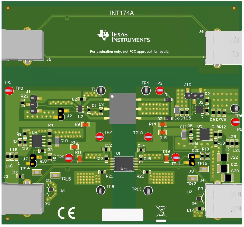
printed-circuit board (PCB) layout top and bottom layers, respectively, and Figure 6-3 shows a 3D
diagram of the PCB indicating how a finished board looks like.
 Figure 6-1 ISOUSB111DWXEVM PCB Layout - Top
Layer
 Figure 6-2 ISOUSB111DWXEVM PCB Layout - Bottom Layer
 Figure 6-3 ISOUSB111DWXEVM - PCB 3D Diagram
 Figure 6-1 ISOUSB111DWXEVM PCB Layout - Top
Layer
 Figure 6-2 ISOUSB111DWXEVM PCB Layout - Bottom Layer
 Figure 6-3 ISOUSB111DWXEVM - PCB 3D Diagram