SLOA317 November 2021 DRV8311
2 SPI Connections in a Multi-Motor System
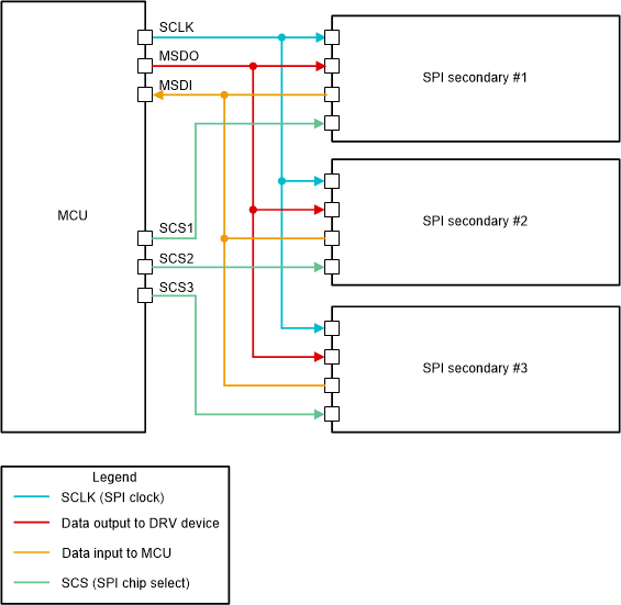
SPI (Serial Peripheral Interface) is a widespread serial communication interface used in many applications, including embedded systems and motor control. In an SPI primary-secondary system, the primary device must provide four wires to a secondary device: a clock signal (CLK), a primary output/secondary input (MSDO), and a primary input/secondary output (MSDI), and a chip select (SCS). A very straightforward implementation of a system with independent secondaries could provide common clock, input, and output signals from the primary device to each secondary device and then assign each secondary device a unique chip select wire. As shown in Figure 2-1, the requirement of a unique serial wire for every secondary device will increase the size and complexity of the system design.
 Figure 2-1 Example of Independent
Secondary SPI System
Figure 2-1 Example of Independent
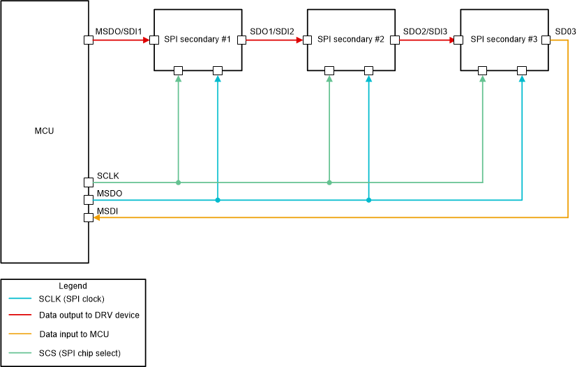
Secondary SPI SystemThese signals do not necessarily need to be unique for each secondary device if more creative architectures are pursued. A common approach is to use daisy-chaining, where secondary devices are essentially pipelined together. As shown in Figure 2-2, in this configuration, the secondary devices relay commands originating from the primary device through the daisy chain in repeated steps.
 Figure 2-2 Example of Daisy-Chained SPI
System
Figure 2-2 Example of Daisy-Chained SPI
SystemDepending up on number of secondary devices in a daisy chain architecture, the primary device can pass the data over several cycles such that the desired commands propagate to the appropriate secondary device. A single common SCS signal from the primary device allows the secondary devices to execute instructions simultaneously. With this setup, no unique wires are required for any secondary device and the entire system only needs four wires for SPI communication. More information on the details of daisy-chain implementations can be found in the Daisy Chain Implementation for Serial Peripheral Interface application report.
Daisy-chaining can successfully reduce the wiring complexity of an SPI implementation by allowing all secondary devices to use only common serial wires. However, daisy-chaining has significant drawbacks in multi-motor control applications, where the MCU is the primary device and motor driver PWM pins are involved for motor control. All devices in a daisy chain must be active at all times to maintain the flow of instructions, so a single inactive device will prevent the system from working properly. It is also not possible to access the daisy-chained secondary devices in a random order. Since these behaviors are undesirable in fast and robust multi-motor control applications, unique PWM wires are still required to be connected directly to the MCU, relegating the function of the SPI interface to only configuration and diagnostics purposes and not addressing the wiring complexity problem discussed in the introduction. The tSPI interface does not suffer from these issues and allows for efficient PWM control completely over a serial interface while maintaining the wire commonality, which will be discussed next.