SLUA475 November 2016 BQ2060A , BQ20Z80 , BQ40Z50-R1 , BQ40Z50-R2 , BQ40Z60 , BQ78350-R1 , BQ78350-R1A
1.1 Closer Inspection
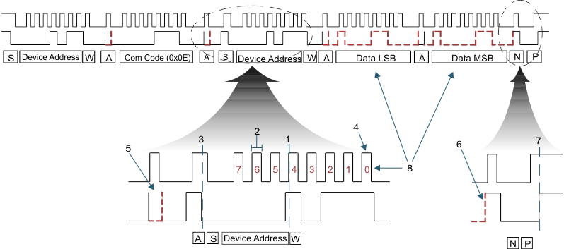
To consider SMBus communication in more detail, Figure 2 shows an SMBus read word and zooms into one byte of a data packet and the NACK/Stop bit. This diagram gives examples of most of the important bits of a total packet.
 Figure 2. SMBus Read Word – Without PEC
 Each byte is 8 bits long. Several things of interest can be derived by looking closely at this diagram:
- Data processing: Each bit of data is processed by the SMBus engine on the rising clock edge. This is where the data is shifted into the engine. Note that the data must never change levels while the clock is high during an SMBus transaction except to create a start, restart, or stop bit.
- Clock timing: The most common cause of difficulty with the SMBus is when host systems fail to follow the SMBus High clock timeout specification. If the clock is high at any time during a transaction for more than 50 µs, the SMBus engine interprets this as a bus idle condition and resets. This SMBus specification requirement can be more problematic than any other.
- Repeated start: The repeated start bit is unique in that it shifts the focus of the current transaction from a write to a read. Prior to the repeated start is a write to a command code with the read/write cleared in the device address, and after the repeated start, the bus shifts to a read of data with the read/write bit set.
- Read/write bit: This bit is appended to the end of the device address. The device address is usually thought of as being 8 bits long, but it is actually 7 bits. So, the device address in an 8-bit format is a 0x16 in a write and a 0x17 after the repeated start in an SMBus read packet.
- Acknowledge: All bytes are followed by an acknowledge (ACK) except for the last byte of a read packet when the host is responsible for NACK-ing the last byte. The slave expects a NACK of this byte even if it is a PEC byte (PEC is explained later in this document). Whoever receives the byte prior to the ACK is who is responsible for sending the ACK.
- No acknowledge: A no acknowledge follows any byte that is not understood by the device receiving the previous data byte. The exception to this rule is the NACK required from the host after the last byte of data in a read packet (see number 5), which indicates to the slave that the host has received all bytes that it expected.
- Start and stop bit: The stop bit is the final bit in the packet. Once this bit is sent by the host, the slave ignores anything on the bus until a start is detected and then only acknowledges its own device. By the SMBus specification, the fuel gauge must always acknowledge its device address.
- Bit order versus byte order: This is important because the orders are opposite, which can be confusing. Each byte starts with the most-significant bit first and ends with the least-significant bit. However, the word of data is sent with the least-significant byte first and the most-significant byte last, which the SMBus specification requires. The bitwise order is normal; however, the bytewise order is in little-endian format as previously explained.