SLUAAI0 January 2022 TPS62810-Q1 , TPS62811-Q1 , TPS62812-Q1 , TPS62813-Q1 , TPS62816-Q1 , TPS628501 , TPS628501-Q1 , TPS628502 , TPS628502-Q1 , TPS628503 , TPS628503-Q1 , TPS628510 , TPS628511 , TPS628512 , TPS62870 , TPS62870-Q1 , TPS62871 , TPS62871-Q1 , TPS62872 , TPS62872-Q1 , TPS62873 , TPS62873-Q1 , TPS62874-Q1 , TPS62875-Q1 , TPS62876-Q1 , TPS62877-Q1 , TPS62A01 , TPS62A01A , TPS62A02 , TPS62A02A , TPS62A06 , TPS62A06A , TPSM82810 , TPSM82813 , TPSM8287A06 , TPSM8287A10 , TPSM8287A12 , TPSM8287A15 , TPSM8287B30
1 Introduction
The loop gain measurement shows the stability and robustness of the control loop of a power supply and provides insight to improve output transient response. For the characterization of the loop, the open loop gain is commonly measured by using the voltage injection method.
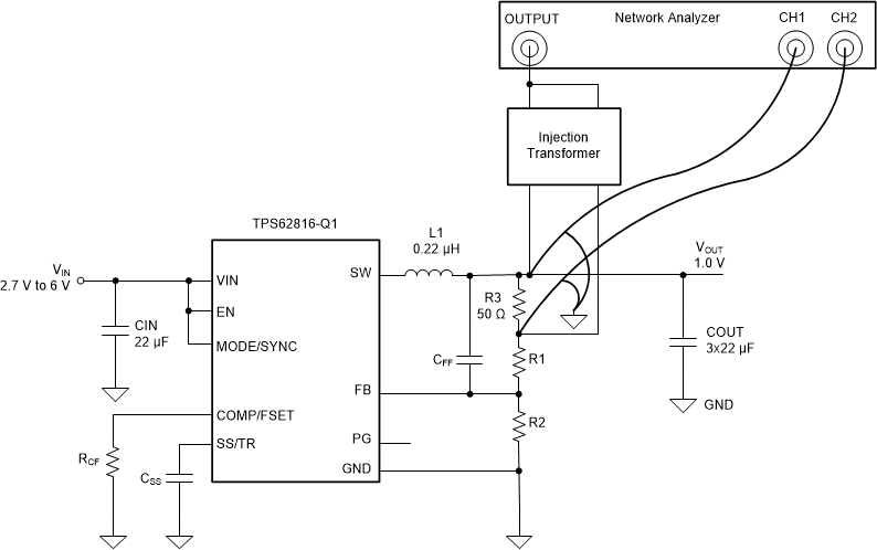
Figure 1-1 shows a common method to measure loop gain of a DC-DC converter, the voltage injection method. This method consists of breaking the control loop in a single place with a resistor and injecting into the loop a sinusoidal disturbance at different frequencies with an injection transformer. Relative magnitudes and phase of the input signal and output signal versus frequency will be subsequently measured.
The voltage injection method approach ensures correct quiescent operating conditions in the system and avoids a common difficulty in systems having a large DC loop gain. However, the limitation is that the voltage injection method requires breaking the control loop by placing an additional resistor at a suitable point.
 Figure 1-1 Output Impedance Setup for TPS62816
Adding additional components could weaken the noise immunity of a device by making the feedback signal trace longer. Thus, making control loop more sensitive to fast switching signals. Besides, the voltage injection approach might not be an acceptable method for space-limited designs.
To avoid breaking the feedback loop, an alternative method is proposed to obtain the loop gain from the output impedance measurements of a DC-DC converter.
The output impedance is an important parameter to characterize a switching voltage regulator and help evaluate how the converter will respond to load changes at different frequencies. Valuable information such as control loop stability, decoupling networks powering the device, dynamic load response and the susceptibility of the power supply to complex loads can be derived from an output impedance measurement.
This application report shows the details of the loop gain measurement of a switching voltage regulator using output impedance measurements and results obtained with TPS62816.