SLUAAK3 January 2024 UCC256402
- 1
- Abstract
- Trademarks
- 1Introduction
- 2UCC25640X HS Pin Has Wide dv/dt Sensing Range
- 3UCC256402/4 Eliminating the Need for the Auxpower
- 4UCC25640X has Higher Vcc Startup Voltage to Support Lower Vcc Capacitance
- 5UCC25640X has Programmable Burst Mode Threshold
- 6UCC256402A Supports Input OVP to Protect PSU if Grid Voltage is Unstable
- 7UCC25640X has Diversity Version for Each Application
- 8Summary
- 9References
2 UCC25640X HS Pin Has Wide dv/dt Sensing Range
As previous mentioned, LED lighting PSU needs to gain the highest efficiency due to thermal concern and the LED also does not have the holdup time requirement so customer increases the magnetizing inductance to reduce the magnetizing circulating current to optimize the efficiency.
LED lighting PSU also needs to support the output voltage range up to two times so resonant tank needs designed for wide gain curve like Figure 2-1 and Figure 2-2 showing. Customers can choose lower Ln to design so the resonant tank curve can be cliffy and can change the Gain a lot with smaller frequency changed.
Designing an LLC Resonant Half-Bridge Power Converterapplication note provides detailed information for designing a resonant half-bridge converter.
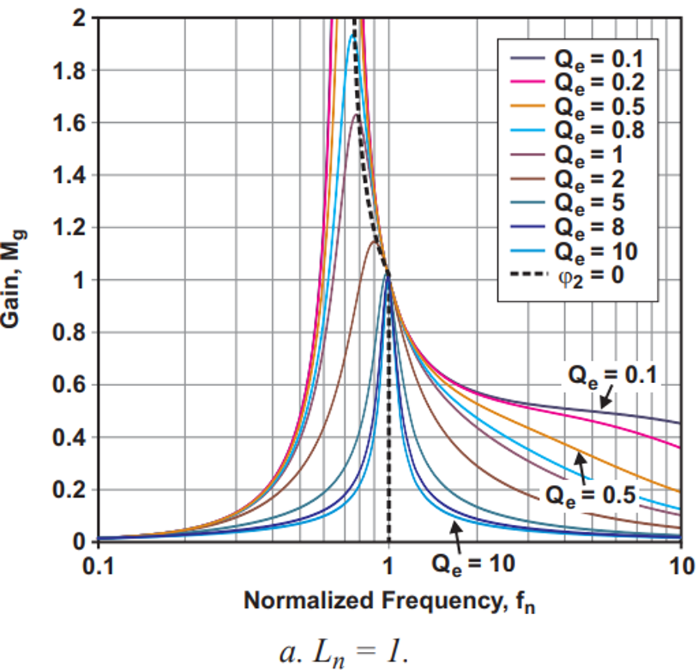 Figure 2-1 LLC Gain Curve
LN=1
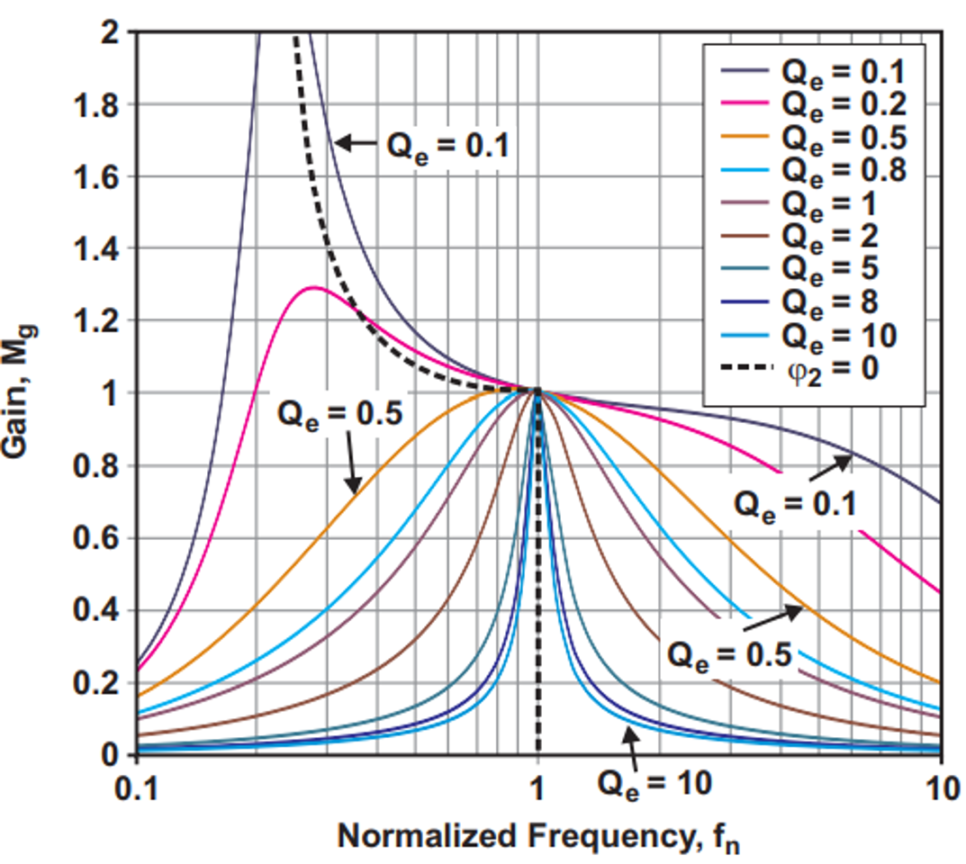 Figure 2-2 LLC Gain Curve
LN=10
Figure 2-2 LLC Gain Curve
LN=10LED lighting PSU also has special requirements about dimming off function which can turn off the LED by reducing the output voltage.
The LED is similar with the diode because the LED requires minimum forward voltage to be conducted, as Figure 2-3 curve showing so customer can control the voltage feedback loop to let the output voltage lower than minimum forward voltage so LED can be turned off.
However, the switching frequency can be increased a lot during the dimming off condition because LED lighting PSU operates at the no load and low Gain condition so the switching frequency as Figure 2-4 showing.
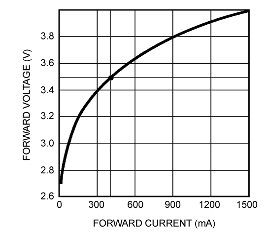 Figure 2-3 LED V-I curve
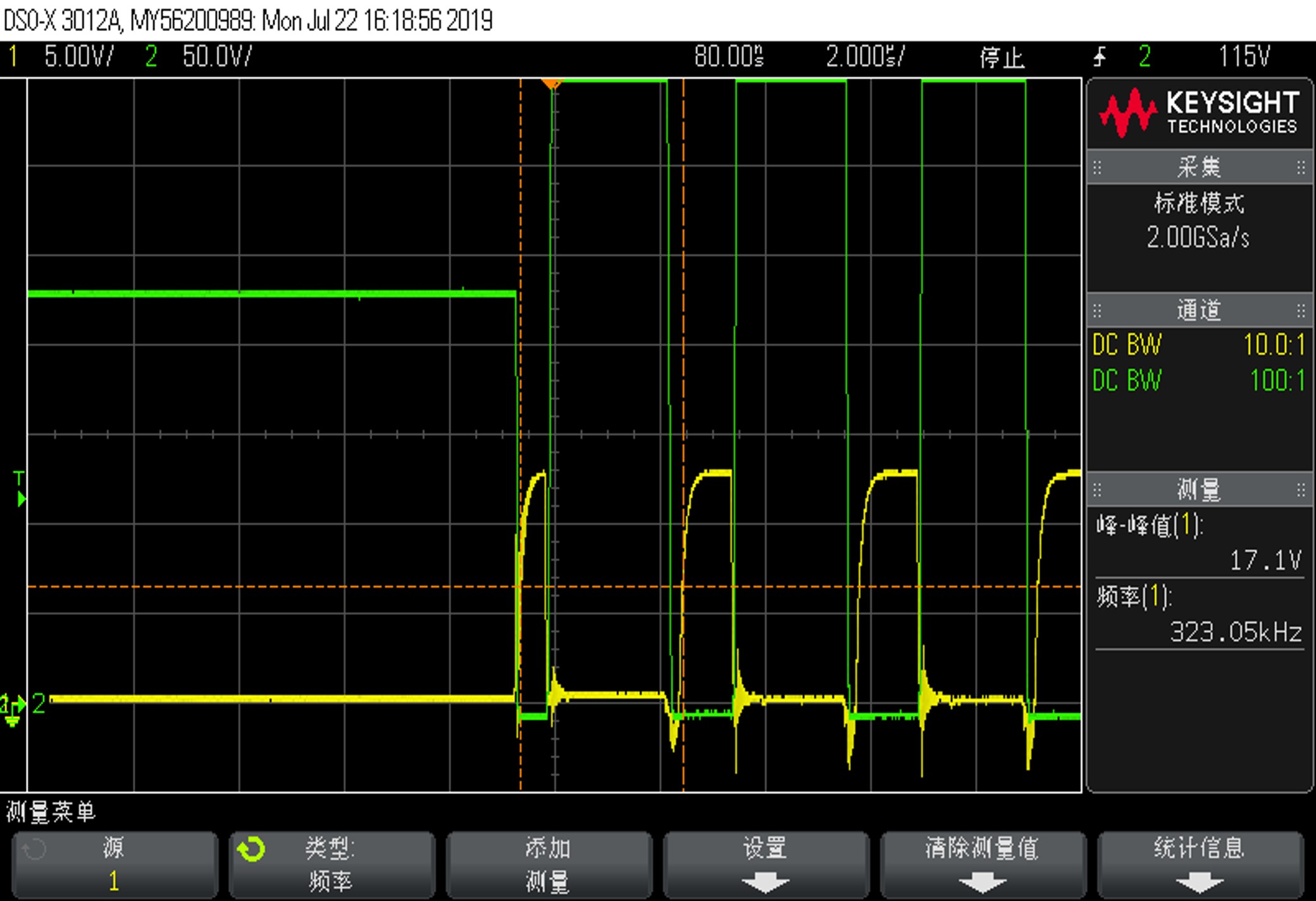 Figure 2-4 Switching Frequency During
the Dimming off
Figure 2-4 Switching Frequency During
the Dimming offIf we consider the resonant tank design and dimming off function for lighting application, the resonant current is pretty small during the dimming off condition.
- Higher magnetizing inductance can reduce the magnetizing circulating current to optimize the efficiency for resonant tank design.
- Higher switching frequency during the dimming off condition
Customer can also add the capacitor to parallel at MOS drain to source for better the EMI performance so the MOS VDS slew rate can be very slow similar to the Figure 2-5 showing. TI is aware of this issue with UCC25630X at customer board so UCC25640X increases the HS pin dv/dt sensing range and can be designed for LED lighting PSU application.
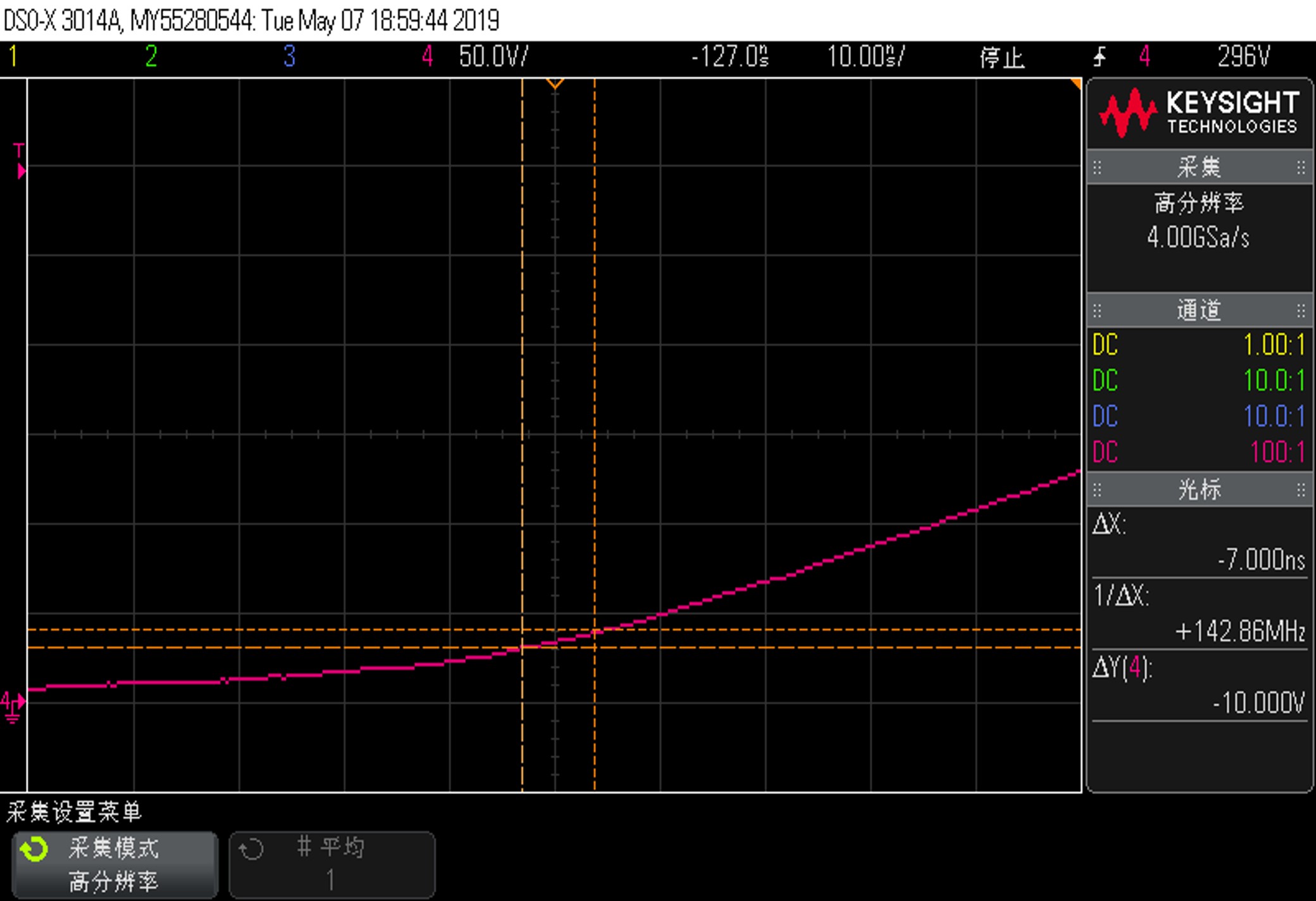 Figure 2-5 MOS VDS Slew Rate