SLUAAO7 March 2023 BQ24640 , BQ25173 , BQ25713 , BQ25798
- Abstract
- Trademarks
- 1Introduction
-
2Supercapacitors Charging Key
Care-Abouts and Implementations
- 2.1 Supercap Charge Profile
- 2.2 Linear Based Supercap Charger
- 2.3 Switch-Mode Buck Converter Based Supercap Charger
- 2.4 Modifying Li-ion Chargers to Charge Supercaps
- 2.5 Using a Li-ion Buck-Boost Integrate FET Charger to Charge a Supercap or Li-ion Battery
- 2.6 Using a Buck-Boost Controller with External FETs to Charge a Supercap
- 3Summary
- 4References
2.6 Using a Buck-Boost Controller with External FETs to Charge a Supercap
Modifying an integrated FET, host controlled buck-buck boost charger to charge a supercap is best if
- The input voltage to the charger can be higher or lower than VREG.
- ICHG is high, typically > 3.0A
- The supercap’s capacitance is very high or very fast charging time is required
If a minimum system voltage is needed, the controller's minimum system voltage can be enabled and set to the lowest acceptable value for the system, to minimize losses across the BATFET.
The BQ25713 block diagram is shown below. The host sets the charge current and supercap voltage regulation, as well as the other settings previously mentioned, in the charger's I2C registers.
 Figure 2-9 BQ25713 Charger Block Diagram
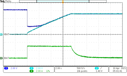
A complete charge cycle using the BQ25713 to charge a 5 F supercap to 5.2 V with ICHG = 3 A from VBUS = 20 V is shown in Figure 2-10.
 Figure 2-10 BQ25713 Charge Cycle of a 5 F Supercap with ICHG = 3 A
As shown in the curve in Figure 2-10, the charger requires a minimum output voltage (approximately 2 V) to supply a given charge current, so V(SYS) is maintained at this level until V(BAT) = V(CAP) rises up to V(SYS). Initially, there is high but slowly decreasing power loss (PL(MAX) = 2 V * ICHG) in the BATFET. The user must select a BATFET which can safely handle this power dissipation, especially if their charge current is high.