SLUUCD0 March 2024 BQ25758
2.5 Equipment Setup

Use the following guidelines to set up the equipment:
- Set power supply #1 for 20 VDC, 8 A current limit and then turn off the supply.
- Connect the output of power supply #1 in series with a current meter to J1 (VIN and PGND).
- Connect a voltage meter across J1 (VIN) and J1 (PGND).
- Connect load #1 in series with a current meter to J3 (VOUT and PGND).
- Connect a voltage meter across J3 (VOUT and PGND).
- Set electronic load to CC mode at 4A. Turn off load #1.
- Connect J5 to the EV2400. Connect J5 to the I2C PORT 2 on the EV2400.
- Make sure the jumpers are installed as indicated in IO and Jumper Descriptions.
- Turn on the computer and power supply #1. Open the bqStudio software.
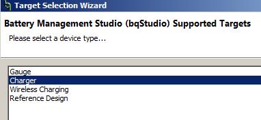
- Select Charger and click the Next button.
- Select Charger_1_00_BQ25758.bqz on the Select a Target Page.
- After selecting the target device, click Field View and then click the Read Register button.

- Select Charger and click the Next button.
- Set WATCHDOG to disabled.

- In 16 Bit Registers, VOUT_REG default is 5000mV
- Buck Test: Set VOUT_REG to 5V (5000mV), measure
V(J1(VAC)) = 20 V ± 0.5 V
I(J1(IAC)) = 1 A ± 0.5 A
V(J3(VOUT)) = 5 V ± 0.5 VI(J3(IOUT)) = 4 A ± 0.5 A
- Buck-Boost Test: Set VOUT_REG to 20V (20000mV), measure
V(J1(VAC)) = 20 V ± 0.5 V
I(J1(IAC)) = 4 A ± 0.5 A
V(J3(VOUT)) = 20 V ± 0.5 VI(J3(IOUT)) = 4 A ± 0.5 A
- Boost Test: Set VOUT_REG to 36V (360000mV), measure
V(J1(VAC)) = 20 V ± 0.5 V
I(J1(IAC)) = 7.2 A ± 0.5 A
V(J3(VOUT)) = 38 V ± 0.5 VI(J3(IOUT)) = 4 A ± 0.5 A