SLUUCE8A February 2021 – October 2021 UCC25800-Q1
- Trademarks
- 1 Description
- 2 Electrical Performance Specifications
- 3 Schematic Diagram
- 4 Description - How to Use
- 5 Test Setup
-
6 Performance Data and Typical Characteristic Curves
- 6.1 Efficiency Result of the LLC Board with External DC Input Voltage
- 6.2 Efficiency Result of the LLC Board with Pre-regulator on Board
- 6.3 Efficiency Typical Results
- 6.4 Output Characteristics
- 6.5 Output Voltage Turn-on at Start Up
- 6.6 Output Ripple Voltage
- 6.7 Frequency Synchronized to External Signal
- 6.8 DIS-pin Enable and Dis-Enable
- 6.9 Load Transient Response
- 6.10 Switch-node Voltage and Current
- 6.11 Over-Current Limit and FLT-pin
- 6.12 CISPR-25 Class-5 Conducted EMI Test Result - Pass
- 6.13 Thermal Images at Full Load
- 7 Transformer Details
- 8 EVM Assembly and Layout
- 9 List of Materials
- 10Revision History
6.12 CISPR-25 Class-5 Conducted EMI Test Result - Pass
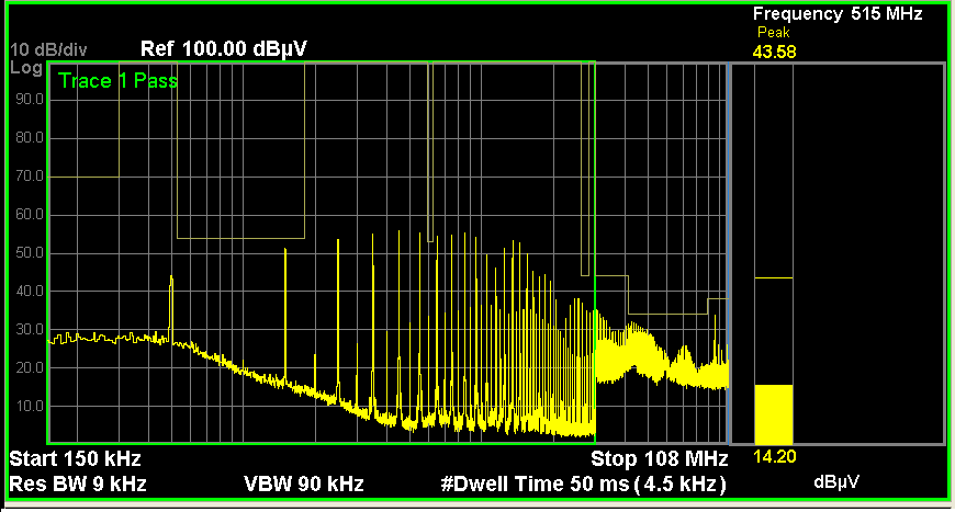
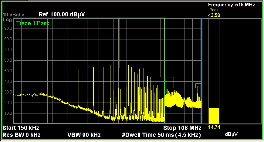
The LLC board EMI test results present a pass in terms of CISPR-25 Class-5 Conducted EMI Peak Limits. The results shown in the below figures are based on the LLC board with L1, D5, R4 and R23 removed, and connect L3 (pin 3 and 4) to J2 and J1. The connection from L3 to J2 and J1 is through a twisted pair of wires.
 Figure 6-19 Peak Limits on Positive Polarity (LLC Board), Pass
 Figure 6-20 Peak Limits on Negative Polarity (LLC Board), Pass
Note:
Please note this was evaluated on an EMI station for pre-qualification purpose only. It is recommended that all final designs be verified by an agency-qualified EMI test house.