SLUUCY5 November 2023 BQ25756E
2.4.3 Equipment Setup - Using a CV Load
Use the following guidelines to set up the equipment:
- Set power supply #1 for 30 V DC, 6 A current limit and then turn off the supply.
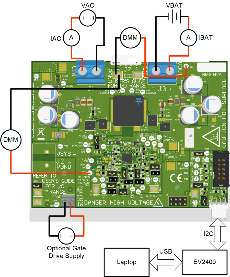
- Connect the output of power supply #1 in series with a current meter to J1 (VIN and PGND).
- Connect a voltage meter across J1 (VIN) and J1 (PGND).
- Connect load #1 in series with a current meter to J3 (VOUT and PGND).
- Connect a voltage meter across J3 (VOUT and PGND).
Set electronics load to CV mode and 23.5 V Turn off Load #1.
Note: Add a 3000uF capacitor on BAT pin when testing without real battery.
- Connect J5 to the EV2400. Connect J5 to the I2C PORT 2 on the EV2400.
- Make sure the jumpers are installed as indicated in IO and Jumper Descriptions.
- Unplug Jumper 13.
- Turn on the computer and power supply #1. Open the BQStudio software.
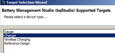
- Select Charger and click the Next button.
- Select Charger_1_00_BQ25756.bqz on the Select a Target Page.
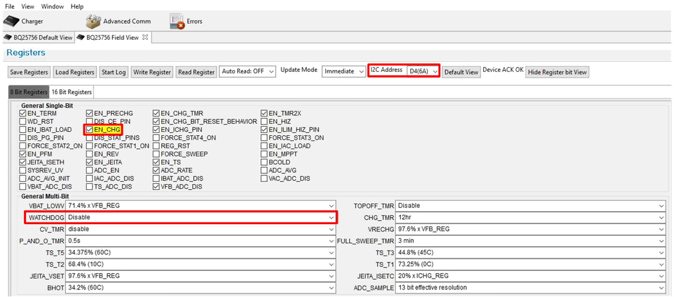
- After selecting the target device, click Field View. The main window of BQ25756E EVM software appears.
- Change I2C Address to D4(6A) and click Read Register.
- Select Charger and click the Next button.
- Set WATCHDOG and EN_CHG to disabled.
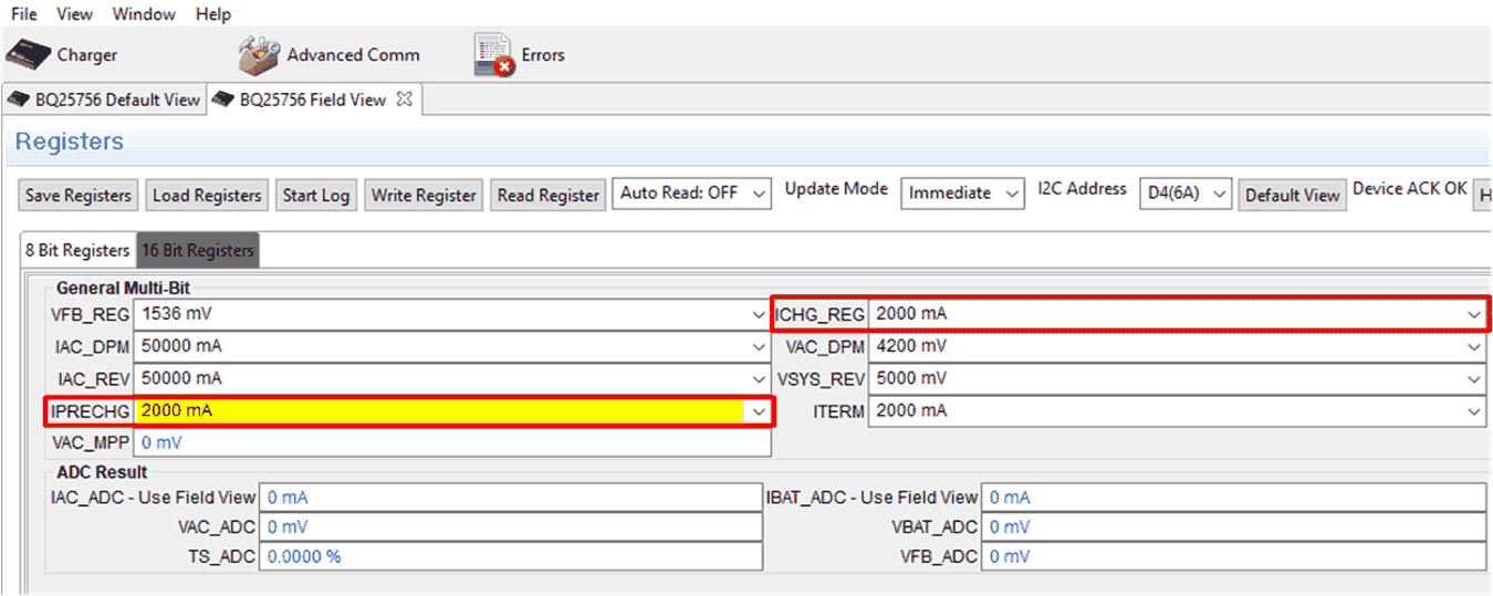
- In 16 Bit Registers, set ICHG_REG to 2000 mA and IPRECHG to 2000 mA.
- Set EN_CHG to enabled. Plug in Jumper 13.
- Set power supply #1 to 30 V, measure
V(J1(VAC)) = 30 V ± 0.5 V
I(J1(IAC)) = 1.6 A ± 0.5 A
V(J3(VBAT)) = 23.5 V ± 1 VI(J3(IBAT)) = 2 A ± 0.5 A
- Set power supply #1 for 23 V, measure
V(J1(VAC)) = 23 V ± 0.5 V
I(J1(IAC)) = 2.1 A ± 0.5 A
V(J3(VBAT)) = 23.5 V ± 1 VI(J3(IBAT)) = 2 A ± 0.5 A
- Set power supply #1 for 10 V, measure
V(J1(VAC)) = 10 V ± 0.5 V
I(J1(IAC)) = 5 A ± 0.5 A
V(J3(VBAT)) = 23.5 V ±1VI(J3(IBAT)) = 2 A ± 0.5 A