SLVA321A August 2011 – April 2021 DRV8811 , DRV8818 , DRV8821 , DRV8823 , DRV8823-Q1
1 Introduction
An H Bridge allows the control of current on both directions through an inductive load such as a motor. Figure 1-1 shows how, by choosing which FET is enabled, current is made to flow in one direction or the other.
 Figure 1-1 H
Bridge
Figure 1-1 H
BridgeDue to the physical properties of inductive loads, once current is flowing in one direction, said direction must be maintained. This is also true when the H Bridge is disabled or when the opposing voltage polarity is applied (e.g. when the Direction command is switched).
Not giving a safe path for this current to flow, while it decays down to zero or switches to the new direction current, will result in damage to the H Bridge’s power switches.
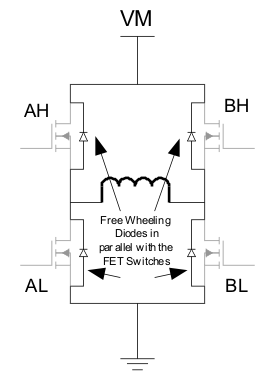
A proper path for this current decay is often offered as free wheeling diodes in parallel with the FET switch, which will start conducting as soon as the FET switches are disabled. A more efficient way to handle this current is to enable/disable FET switches in a sequence that carries the decaying current, but without causing shoot through.
 Figure 1-2 Free
Wheeling Diodes
Figure 1-2 Free
Wheeling DiodesThese alternatives to control current flow until it decays are referred to as current recirculation methods. On this application note we will detail each style of current recirculation and decay modes.