SLVAE50A February 2019 – April 2022 ESDS302 , ESDS312 , ESDS314
3.1 Surge Protection Diode on Secondary Side of Transformer
Therefore since it can be seen that although the pulse that is transferred through the transformer is reduced in peak and width, it could still potentially damage the phy. Using the same surge set up and adding in the ethernet phy, the picture below shows the point just before and after it breaks the device. Notice that the voltage that is measured on the secondary side is relatively high. This is due to the high clamping voltage of the internal ESD protection of the phy. The waveforms below were taken measuring the current on the primary side in blue, the current on the secondary side in green and the voltage on the secondary side in yellow.
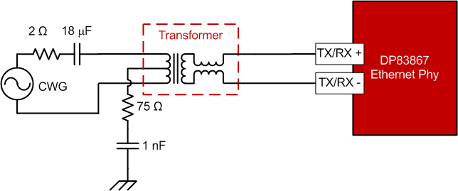 Figure 3-4 Surge Pulse Setup with Transformer and Ethernet Phy
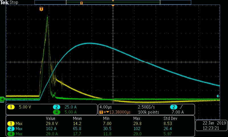 Figure 3-6 Diff Surge Pulse After Phy Breaks
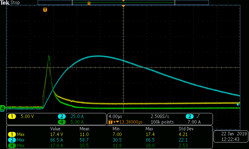 Figure 3-5 Diff Surge Pulse Just Before Phy Breaks
Rerunning the same test but adding in the ESDS314 onto the signal lines that the surge was applied to, it can be seen that the device is protected from this event.
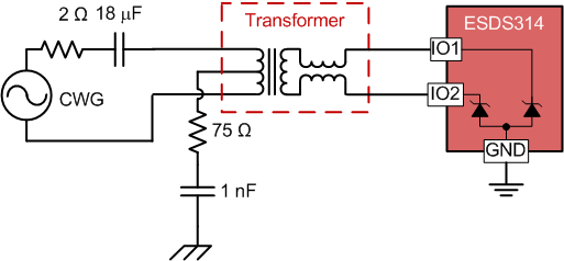 Figure 3-7 Surge Setup with Ethernet Physical Layer and ESDS314
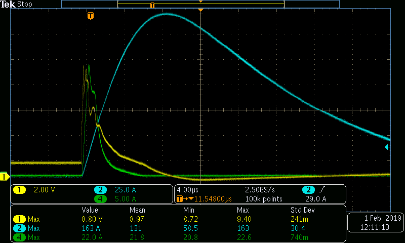 Figure 3-9 ESDS314 Protecting Phy From Differential Surge Pulse at 160 A
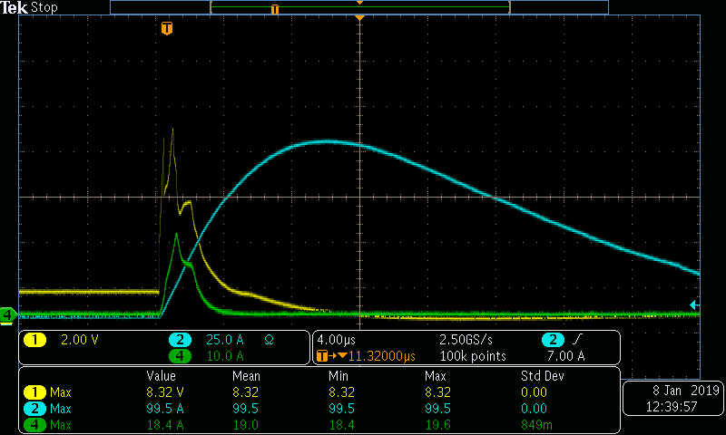 Figure 3-8 Differential Surge Waveform with ESDS314 and Phy