SLVAEG2A August 2019 – May 2021 LM10011 , TPS53515 , TPS53915 , TPS543B20 , TPS543C20A , TPS54424 , TPS544B20 , TPS546D24 , TPS546D24A , TPS54824 , TPS548A20 , TPS549A20 , TPS549B22 , TPS549D22 , TPS54A24
4 Current Sharing
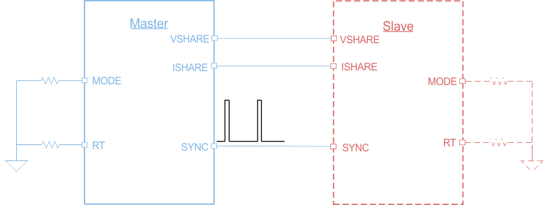
When two devices operate in a dual-phase, stackable application, a current-sharing loop maintains the current balance between devices. Both devices share the same internal control voltage through VSHARE pin. The sensed current in each phase is first compared in a current-share block by connecting the ISHARE pin of each device, and then the error current is added into the internal loop. Connect the SYNC pin of the master and slave converters to share switching frequency information. The resulting voltage is compared with the PWM ramp to generate the PWM pulse for DC/DC conversion. Figure 4-1 shows the TPS543C20A in a stackable configuration to current-share up to 80-A while operating 180 degrees out of phase. Not only does a stackable configuration support higher currents, but it also reduces input ripple with out-of-phase operation, and improves overall system thermal performance, since the generated heat is spread over more circuit board area. If higher current is desired from an integrated MOSFET DC/DC converter, the TPS546D24A can be stacked up to four devices to support up to 160 A. For more information, see the reference design PMP21814.
 Figure 4-1 TPS543C20A in Stackable Configuration Supports up
to 80 A