SLVAET3 October   2021 TPS8802


  1.   Trademarks
  2. 1Introduction
  3. 2System Architecture
    1. 2.1 Battery Voltage
    2. 2.2 VCC Supply
      1. 2.2.1 Connecting VCC to VBST
      2. 2.2.2 Connecting VCC to VBAT Through a Switch
    3. 2.3 MCU Supply
      1. 2.3.1 MCU Connected to VBAT
      2. 2.3.2 MCU Connected to MCU LDO
      3. 2.3.3 MCU with VCC Connected to VBAT Through a Switch
    4. 2.4 Photoelectric Smoke Sensor LED Supply
      1. 2.4.1 LED Connected to VBAT
      2. 2.4.2 LED Connected to PLDO
      3. 2.4.3 LED Connected to LEDLDO
    5. 2.5 Example Schematics
      1. 2.5.1 Smoke and CO Schematics
      2. 2.5.2 Smoke-Only Schematics
  4. 3Current Consumption
    1. 3.1 Standby Current
      1. 3.1.1 TPS8802 Standby Current
      2. 3.1.2 Microcontroller Standby Current
    2. 3.2 Measurement Current
      1. 3.2.1 Smoke Measurement Current
      2. 3.2.2 CO Measurement Current
      3. 3.2.3 Battery Test Current
      4. 3.2.4 User Alarm Test Current
    3. 3.3 Other Current Consumption
      1. 3.3.1 Boost Charge Current
      2. 3.3.2 Initialization Current
  5. 4System Power Calculation and Measurements
    1. 4.1 Power Calculation Spreadsheet
      1. 4.1.1 Power Consumption Overview Page
      2. 4.1.2 Detailed Calculation Pages
    2. 4.2 Power Consumption Measurements
      1. 4.2.1 Power Measurement Method
      2. 4.2.2 Smoke and CO System Measurements
      3. 4.2.3 Smoke-Only System Measurements
  6. 5Summary
  7. 6References

Photoelectric Smoke Sensor LED Supply

The photoelectric smoke sensor LED can be powered by the battery, PLDO, or LEDLDO. For maximum power savings, the LED should be supplied directly from the battery if the voltage supports it. If direct battery voltage is not supported, use the boost converter with VBST set to the minimum required voltage. Before selecting how to power the LED, the minimum LED supply voltage VLED(min) must be calculated using Equation 1. VF is the LED forward voltage, VDINA(drop) is the LED driver dropout voltage (300 mV at 150 mA and 500 mV at 500 mA), VCSA is the voltage at the CSA current sense pin, and ΔVLED is the voltage drop caused by the capacitive voltage supply on the LED. Using a higher capacitance on the LED supply decreases the supply voltage drop when pulsing the LED as shown in Equation 2.

Equation 1. GUID-20200904-CA0I-3TQ8-SF2Q-P3V9MFJGWBNB-low.gif
Equation 2. GUID-20200904-CA0I-BFVG-ZTSX-MS4G5JCJGXKC-low.gif
GUID-20200904-CA0I-RCTL-JVWB-8ZNLNGFJZXTG-low.gif 
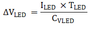
Figure 2-4 LED Supply Selection Guide