SLVAEX7A December 2020 – January 2023 OPA2310 , OPA310 , OPA348 , OPA4310 , TLV341 , TLV341A , TLV342 , TLV342A
4 How to Measure the ESD Structure Current of an Op Amp
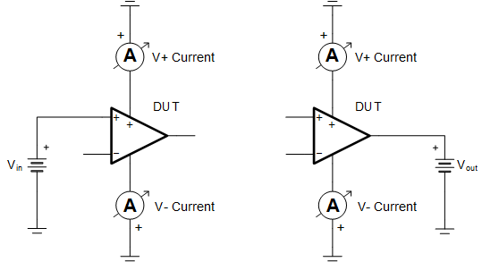
The ESD structure current of an op amp can be measured to better understand the behavior of its ESD protection circuitry. One method of measurement involves picking an amplifier, grounding the supply pins, and sweeping the voltage at the input and output pins, one pin at a time. The pins not under test can be left open. Measuring the corresponding current passing through the V+ and V- pins shows the amount of ESD structure current. This setup is shown in Figure 4-1 and gives an idea of the amplifier behavior when the amplifier is turned off with grounded supply pins and an input or output signal is still present. To avoid damaging the device during testing, it is a good idea to limit the current available from the voltage source to ±10 mA. In production, it is better to limit the current to ±1mA when possible. This test method was used to confirm the input structure behavior of some devices and the sample data can be found in Appendix A.
 Figure 4-1 Setup 1 - Example Schematic for Testing IN+ and OUT Pins With Grounded Supplies
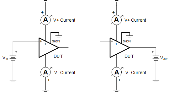
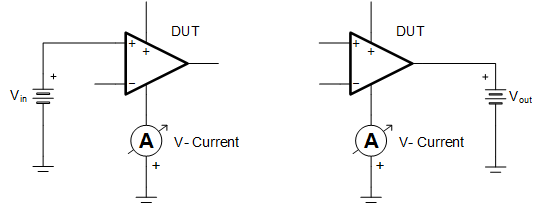
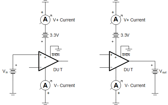
Depending on how the amplifier is turned off, a different test setup may be more appropriate for accurately observing the ESD structure current while an input or output voltage is present. For example, a shutdown pin may allow the circuit designer to put the amplifier into shutdown mode while the V+ supply pin still has a voltage present. Alternatively, some circuit designers look to turn off their amplifiers by switching open the V+ pin. Alternate ESD structure current test setups for some of the more popular scenarios are shown in Figure 4-2 through Figure 4-4. Sample data for these test setups is also available in Appendix A.
 Figure 4-2 Setup 2 - Example Schematic for Testing IN+ and OUT Pins With Grounded Supplies and Shutdown Pin
 Figure 4-3 Setup 3 - Example Schematic for Testing IN+ and OUT Pins With Open V+ Pin and Grounded V- Pin
 Figure 4-4 Setup 4 - Example Schematic for Testing IN+ and OUT Pins With Power on V+ Pin, Grounded V- Pin and Shutdown Pin Low