SLVU240B May 2008 – August 2018 MSP430F2131 , TPS62260
4.1.1 LED Power Stages
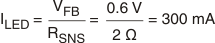
Because the brightness of an LED is determined by the current flowing through it, not the voltage across it, LEDs tend to be powered by current sources in all the simplest of applications (that is, when uniform intensity and color balance are not important). In this application, each power stage uses a TPS62260 DC/DC converter configured as a controllable current source. Instead of using a resistor divider between the output and GND to generate the feedback voltage, a small current-sensing resistor is inserted between the LED cathode and GND. In this configuration, the TPS62260 controls its duty cycle at whatever value is needed to regulate the voltage across the current-sensing resistor to 0.6 V (the internal reference voltage of the IC). Using a 2-Ω current-sensing resistor, the LED current is therefore regulated to a value given by:
Brightness is varied by pulse width modulating the current flowing through each LED. This approach has two main advantages compared with using analog methods to control LED current.
First, the color balance of an LED changes with the current flowing through it, so not only is the brightness of an LED at 10 mA different than at 100 mA, its color is, too. With pulse width modulation (PWM) dimming, the current flowing through the LED when it is active is always the same so its color does not change. As long as the dimming frequency is high enough, the only effect the human eye sees is a variation in LED intensity. In this application, a nominal dimming frequency of 122 Hz is used.
Second, it is simpler and cheaper to generate three PWM signals using a microcontroller than three analog voltages, which would require a 3-channel DAC.
The PWM dimming scheme works as follows:
- When the NET_DIMM_LED1 signal is low, D1 blocks any current flow away from the FB pin and U2 regulates LED current to its full-scale value of 300 mA (see Equation 1).
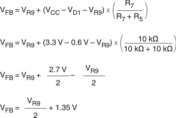
- When NET-DIMM_LED1 is high (close to the 3.3-V supply voltage of U2) the U2 FB pin is held at 1.35 V, which forces the duty cycle of U2 and consequently the LED current to zero (see Equation 2).
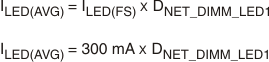
The average current flowing through the LED and its brightness are simply the products of the full-scale (FS) LED current multiplied by the duty cycle of the dimming signal (NET_DIMM_LED1):