SLVUBX8B October 2020 – December 2021 TPS2661
- Trademarks
- 1Introduction
- 2Description
- 3Schematic
- 4General Configurations
-
5Test Setup and Procedures
- 5.1 Overload Protection Test
- 5.2 Output Short-Circuit Test
- 5.3 Input Undervoltage Protection Test
- 5.4 Output Undervoltage Protection Test
- 5.5 Output Overvoltage Protection Test
- 5.6 TPS26612 Overload Protection Test
- 5.7 Current Limiting for VIN < –Vs
- 5.8 Surge Protection Test (Current Input, CH1)
- 5.9 Surge Protection Test (Analog Output, CH2)
- 6EVAL Board Assembly Drawings and Layout Guidelines
- 7Bill Of Materials (BoM)
- 8Revision History
5.1 Overload Protection Test
Use the following instructions to evaluate current limit behavior of the TPS26610 (U1):
- Set the jumper setting J4 in 2–3 position to set MODE = 180 kΩ
- Install jumper J6 in 1-2 position to connect 49.9 Ω as burden resistor
- Set dual polarity regulated power supply to +15 V : 0 V : –15 V and apply the power at connector J2
- Apply a voltage of 1.6 V at I_IN_1 and then step-up to 8 V to emulate overload situation on TPS26610
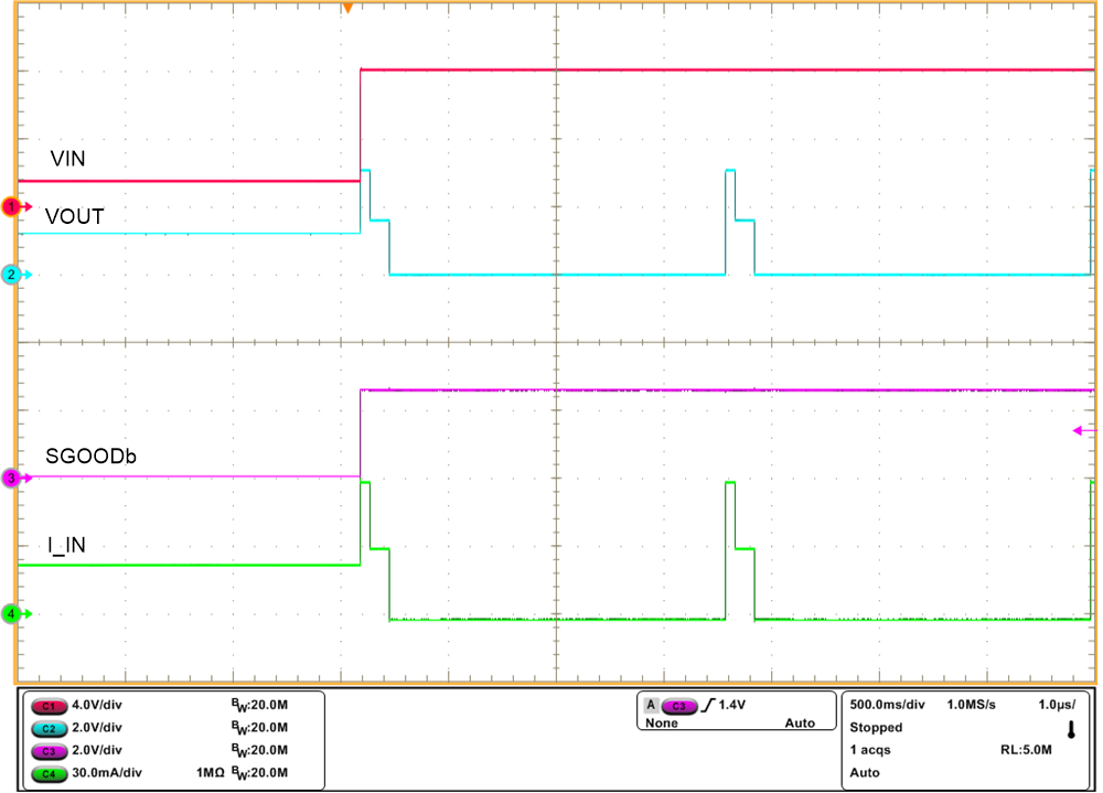
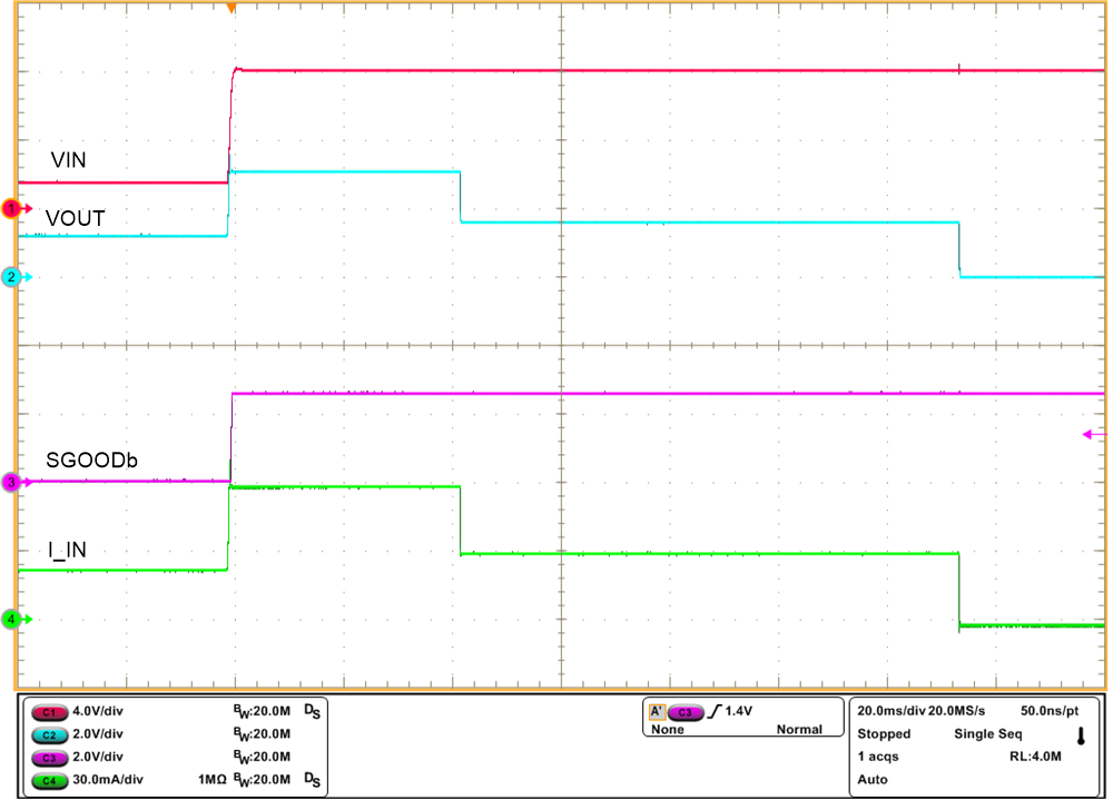
- The device limits the current to 60 mA for approximately 50 ms and after that the current is limited to 30 mA for approximately 100-ms time and then auto retries for every 1.6 s
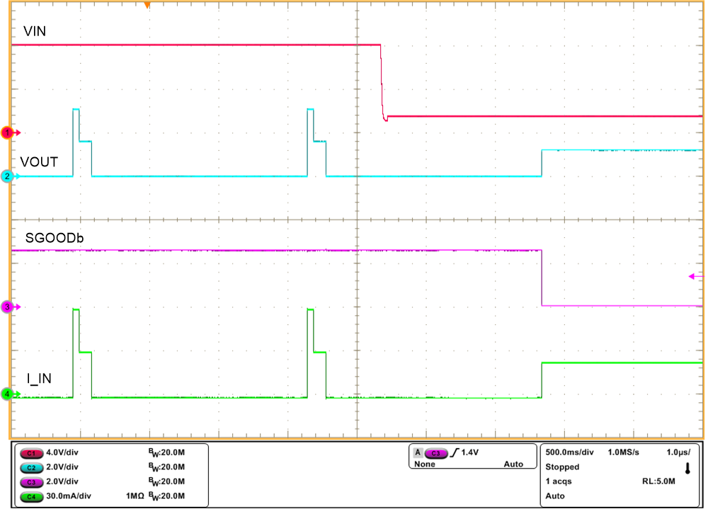
- Step-down the voltage at I_IN_1 to 1.6 V to remove the overload fault
Figure 5-2 and Figure 5-3 show current limit behavior captured on the TPS2661EVM eFuse Evaluation Board. Figure 5-4 shows device response during recovery from overload fault.
 Figure 5-2 Current Limit Behavior of
TPS26610 for IOUT > 2 × IOLWith MODE = 180 kΩ
  Figure 5-3 Current Limit Behavior of TPS26610 for IOUT > 2 ×
IOL With MODE = 180 kΩ (Zoomed)
 Figure 5-4 TPS26610 Response During Recovery From Overload Fault