SLVUBY2A July 2020 – November 2020
3.1 ADCin Setting (S1)
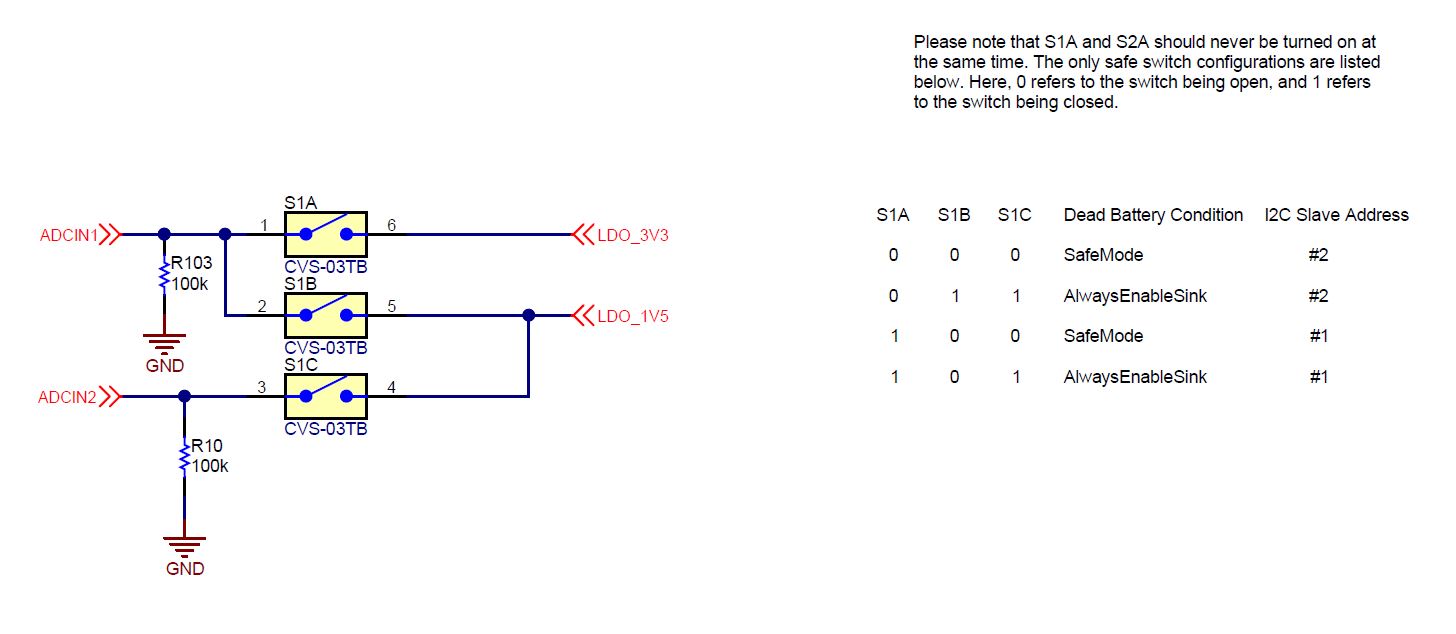
During the boot procedure, the TPS25750 will read the ADCINx pins and set the dead battery configuration and the I2C slave address for the PD controller based off of the pin inputs. The switch bank S1 can be switched to enable different dead battery conditions and I2C slave addresses. Keep in mind that S1A and S2A should never be turned on at the same time. The only safe switch configurations are listed below. A switch condition of 0 refers to the switch being open and a switch condition of 1 refers to a closed switch. These are also labeled on the EVM.
The two dead battery configurations offered are Safe Mode and Always Enable Sink. Their functions are listed below.
Always Enable Sink: The device always enables the sink path regardless of the amount of current the attached source is offering. USB PD is disabled until configuration is loaded.
Safe Mode: The device does not enable the sink path. USB PD is disabled until configuration is loaded. Note that the configuration could put the device into a source-only mode.
|
S1A | S1B | S1C |
Dead Battery Configuration | I2C Slave Address |
|---|---|---|---|---|
0 | 0 | 0 | Safe Mode | #2 |
0 | 1 | 1 | Always Enable Sink | #2 |
1 | 0 | 0 | Safe Mode | #1 |
1 | 0 | 1 | Always Enable Sink | #1 |
These two options are set with S1. The schematic for the ADCIN setting is shown below.
 Figure 3-2 ADCIN S1 Connections