SLVUCE2 May   2022


  1.   Trademarks
  2. 1What You Get
  3. 2What You Need In Addition
  4. 3How to Get Started
    1. 3.1 Hardware Setup
      1. 3.1.1 Communication without CAN Transceiver
      2. 3.1.2 Communication with CAN Transceiver
    2. 3.2 Software Installation
      1. 3.2.1 Run Applications Through Online
      2. 3.2.2 Run Applications on Desktop
    3. 3.3 Firmware Update
    4. 3.4 GUI Function
      1. 3.4.1 Connection Status
      2. 3.4.2 LED Control Page
      3. 3.4.3 Diagnostics Page
      4. 3.4.4 EEPROM Programming Page
      5. 3.4.5 Registers Page
      6. 3.4.6 Debug Page
  5. 4Board Layout
    1. 4.1 Schematic
    2. 4.2 BOM

LED Control Page

Figure 3-12 shows the registers page.On the left side, you can select one or more channels to control. On the right side, you can change the current and PWM of the selected channel. The ADC value and error flag is shown on the right. The green button called "Device Configuration" is used to make an advanced setup.
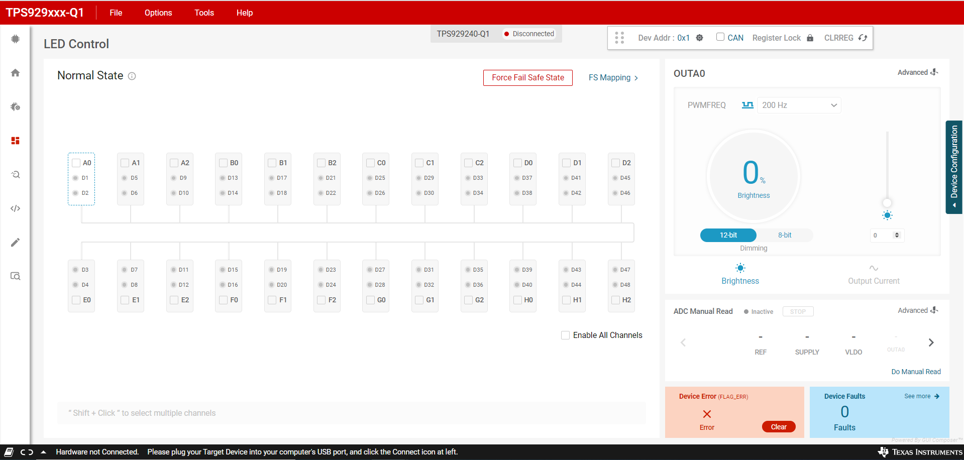
GUID-20220504-SS0I-8BBG-HB1Q-W6TRPTHNLMBW-low.png Figure 3-12 TPS929240EVM GUI LED Control Page