SLYT803B october 2020 – october 2020 BQ24610 , BQ25713 , BQ25790 , LM66100 , LM74700-Q1
- 1
- 1 Introduction
- 2 Understanding Battery Packs
- 3 Stackability Requirements for Battery Packs
- 4 A Multibattery Management System Design
- 5 Battery Charging
- 6 Battery Gauging and Protection
- 7 DC-to-DC Converter or Controller Stage (Boost or Buck-boost Stage)
- 8 ORing Control
- 9 Load Sharing
- 10Conclusion
- 11References
- 12Related Web Sites
9 Load Sharing
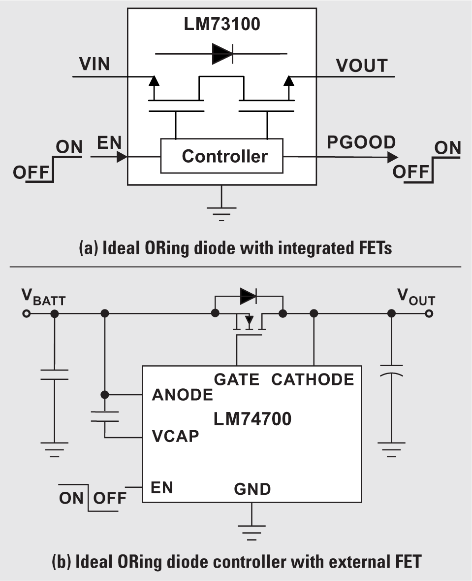
When employing ORing control without load sharing, it is possible to have all of the FETs on at once if the path voltages are well matched. But the different capacities, voltage levels and accuracy of the cells can make it very difficult to balance current among the path. Each parallel path can charge and discharge at slightly different rates depending on the output load condition. Properly balancing and sharing the load across multiple paths is important.
 Figure 4 Two ORing Configurations
Accurate load sharing between the battery paths and active ORing with the main input voltage enables the use of standardized circuits across several platforms, reducing time to market. The resulting modularity provides great flexibility, making it easy to reconfigure systems to accommodate a broad variety of output-voltage and load-current combinations. The expandability of such a system provides a simple way to keep up with increasing load-current requirements. Load sharing also facilitates redundancy and eases thermal management because of smaller battery units.
Overall, load sharing improves system performance. It also helps in air shipments of smaller units that can be combined at the receiving end.
Finally, depending upon the input and output specifications, one more DC-to-DC converter (or controller) can power the front- and back-end units of ultrasound scanners.