SLYT819 October 2021 BQ25980
- 1 Introduction
- 2 Delivering over 100 W power with USB PD
- 3 High-efficiency switched-capacitor DC/DC converters
- 4 Output impedance
- 5 Switching losses
- 6 Dual-phase interleaved switched-capacitor converter
- 7 High-power-density switched-capacitor converter
- 8 Switched-capacitor converter application: fast charging for portable devices
- 9 Conclusion
- 10Related Websites
- 11Important Notice
4 Output impedance
There are two asymptotic limits in the output impedance: the slow switching limit and the fast switching limit. The slow switching limit is dominated by the charging sharing loss in the capacitors, assuming that the resistance in the converter is zero. The fast switching limit is dominated by the conduction loss, assuming that the capacitance is infinite and the voltage across the capacitor is constant [3].
A charge flow vector method derived in [3] calculates the slow and fast switching limits. Equation 1 and Equation 2 express charge flows in the capacitors and switches with respect to output charge and current:
where, and are the capacitor and switch charge flow vectors in phase j, and ac and ar are the charge multiplier vectors.
Figure 4-1 illustrates the charge flow in the flying capacitor and switches Q1 through Q4 for the 2-to-1 switched-capacitor converter. The duty cycle for both the charging and discharging phases is fixed at 50%.
Based on Figure 4-1, the input charge is half the output charge. Equation 3 expresses the capacitor charge multiplier, ac:
Equation 4 expresses the switch charge multiplier, ar:
After obtaining the charge multiplier, Equation 5 and Equation 6 calculate the slow and fast switching limits, with details of the analysis available in [3].
The real switched-capacitor converter contains both charge-sharing loss and conduction loss. Equation 7 could approximate the output resistance for converter design purposes [4], with RSSL the slow switching limit calculated at the given converter switching frequency.
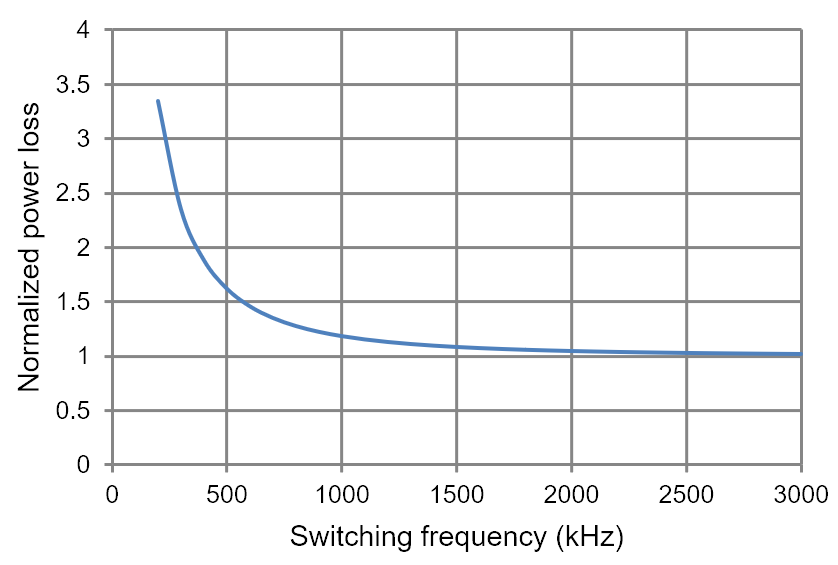
Figure 4-2 is the power loss based on the output impedance of the 2-to-1 switched-capacitor converter over the switching frequency. The power loss of the fast switching limit is normalized to 1. The power loss continues to drop as the frequency increases because the fast switching limit is inversely proportional to the switching frequency. In a real application, however, you would need to include the switching loss to select the switching frequency.
 Figure 4-2 Output impedance power loss
of the 2-to-1 switched-capacitor converter.