SLYU043C April 2020 – October 2021 DRV5013 , DRV5023 , DRV5032 , DRV5053 , DRV5055 , DRV5055-Q1 , DRV5056 , DRV5056-Q1 , TMAG5231
1 HALL-ADAPTER-EVM Usage Instructions
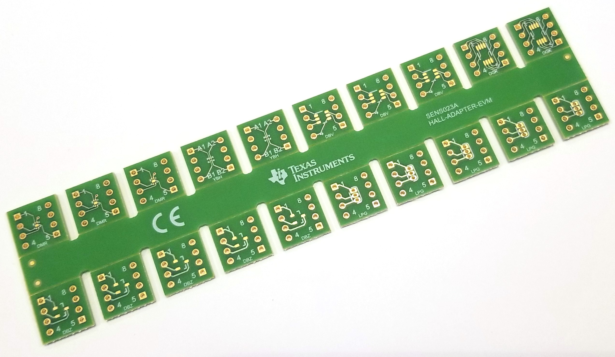
The HALL-ADAPTER-EVM simplifies prototyping SMT ICs:
| The HALL-ADAPTER-EVM supports SOT23-3 (DBZ), TO-92 (LPG), X2SON (DMR), SOT23-5/6 (DBV), DSBGA (YBH) and MSOP-8 (DGK) packages. |
|
||
Usage Instructions:
|
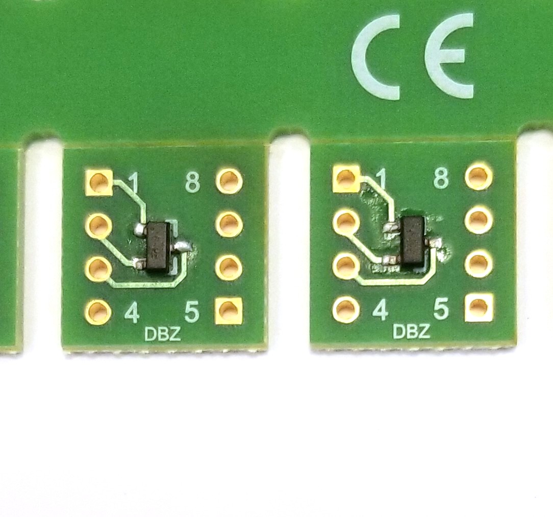
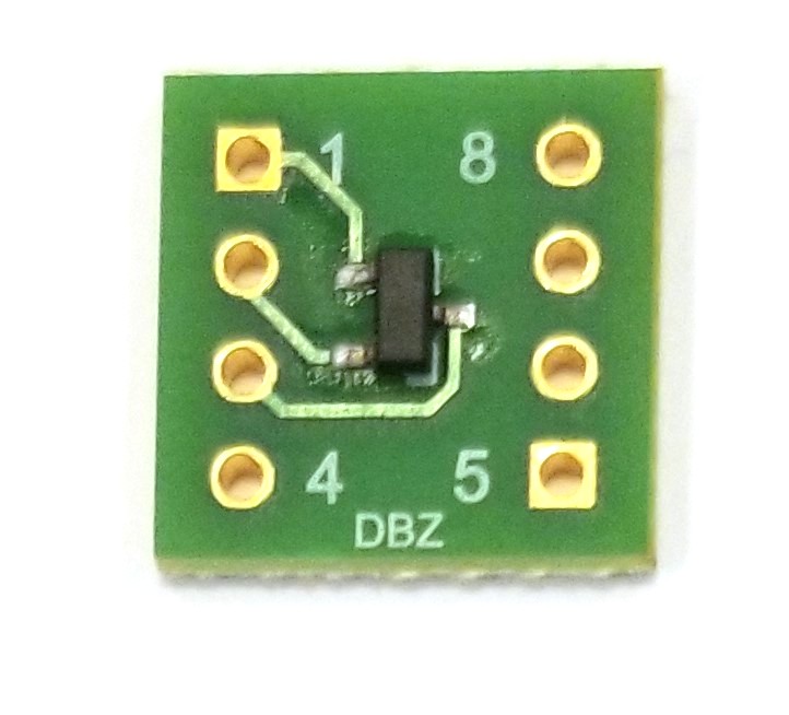
Step 1: Solder IC(s) to adapter PCB. Also solder any necessary decoupling capacitor needed for the device. Refer to the device data sheet for appropriate decoupling capacitor values. ICs may be hand-soldered or attached with IR or hot air reflow techniques. | ||||
|
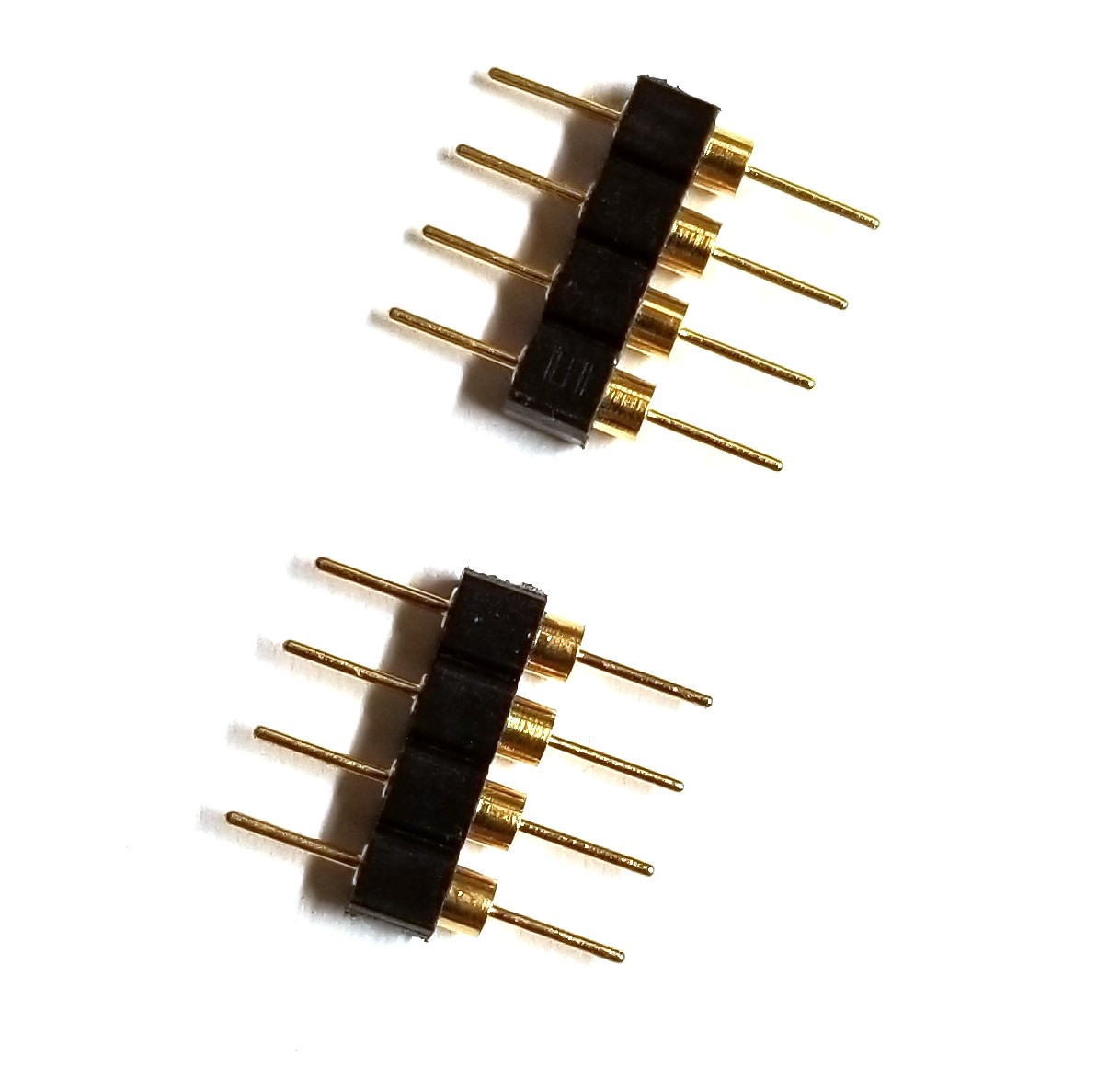
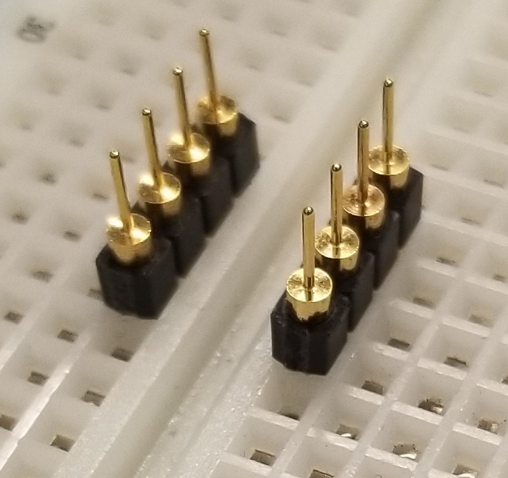
Step 2: Use long nose pliers to snap terminal strips (Samtec part number TSW-124-07-L-S) into 4 position lengths. | ||||
|
Step 3: Gently flex panel at score lines to separate boards. | ||||
|
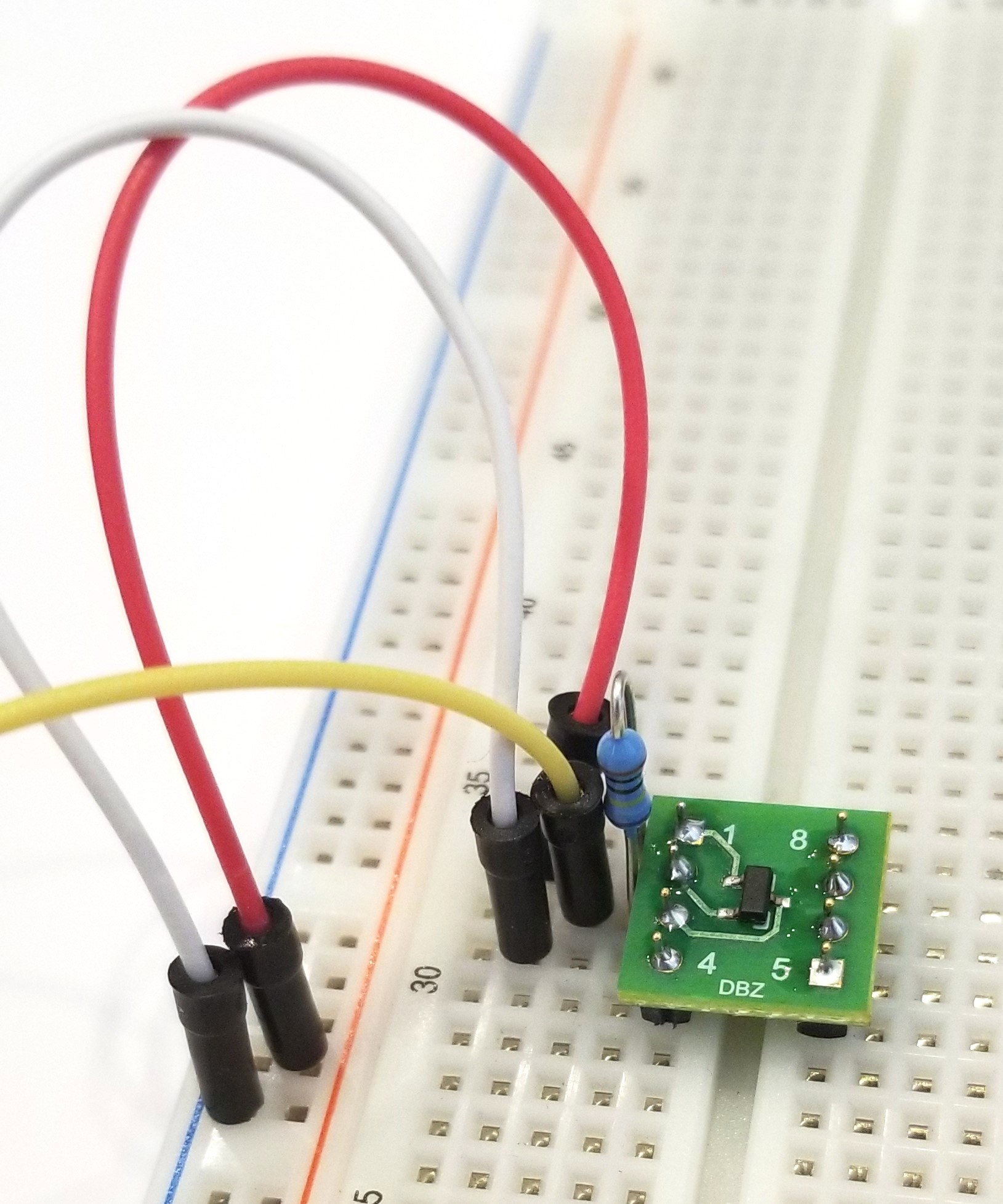
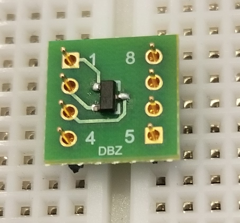
Step 4: Insert terminal strips into a breadboard or spare DIP socket to align pins. | ||||
|
Step 5: Position board over pins and solder the connections. Carefully remove from breadboard or DIP socket and complete. | ||||