SNOAAA7 April   2024 LMG3522R030


  1.   1
  2.   Abstract
  3.   Trademarks
  4. 1Introduction
  5. 2Overview of Inverter Model
    1. 2.1 Power Stage
    2. 2.2 Control and Modulation Method
  6. 3Realization of Digital Control Using C-Script Block
    1. 3.1 Overview of Project Structure
    2. 3.2 AC Voltage Sampling and True RMS Value Calculation
    3. 3.3 Multiple Loop Control
      1. 3.3.1 Voltage Loop With Notch Filter
      2. 3.3.2 Current Loop With PI Compensator Anti-Windup
      3. 3.3.3 Sinusoidal and Sawtooth Wave Generator
      4. 3.3.4 Totem-Pole Modulation and Dead-Time Control
  7. 4Simulation Results
  8. 5Summary
  9. 6References

Current Loop With PI Compensator Anti-Windup

Current loop is connected after the voltage loop. The updated rate is set to 100kHz, so the sample rate of the inductor current is also 100kHz. The output signal of the notch filter multiplied by the sinusoidal wave created by the sinusoidal module creates the reference current signal. Similar to the voltage loop, current error signal is processed by the PI compensator. To avoid oversaturation of integral, an anti-windup is used in the PI compensator. Figure 3-10 shows the code for the current loop.
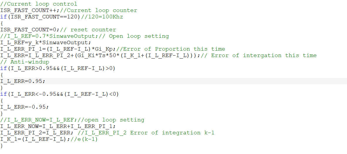
GUID-20240319-SS0I-1TZL-RLCM-BM9KZLXMNSBK-low.pngFigure 3-10 Current Loop Code