SNVU836A March   2023  – April 2024 LP5891-Q1


  1.   1
  2.   Description
  3.   Features
  4.   Applications
  5.   5
  6. 1Evaluation Module Overview
    1. 1.1 Introduction
    2. 1.2 Kit Contents
    3. 1.3 Specification
    4. 1.4 Device Information
  7. 2Hardware
    1. 2.1 Function Descriptions
    2. 2.2 Test Setup
      1. 2.2.1 System/Tool Requirements
      2. 2.2.2 Hardware Setup for Single Device
      3. 2.2.3 Hardware Setup for Dual Cascaded Devices
  8. 3Software
    1. 3.1 Software Setup
  9. 4Hardware Design Files
    1. 4.1 Schematic
    2. 4.2 PCB Layout
    3. 4.3 Bill of Materials
  10. 5Additional Information
    1. 5.1 Additional Resources
    2. 5.2 Trademarks
  11. 6Revision History

Function Descriptions

This section describes the connectors, jumpers, and switches on the LP5891Q1EVM board.

Figure 3-1 shows the image of the driver IC side of the LP5891Q1EVM board.

Figure 3-2 shows the image of the LED side of the LP5891Q1EVM board.
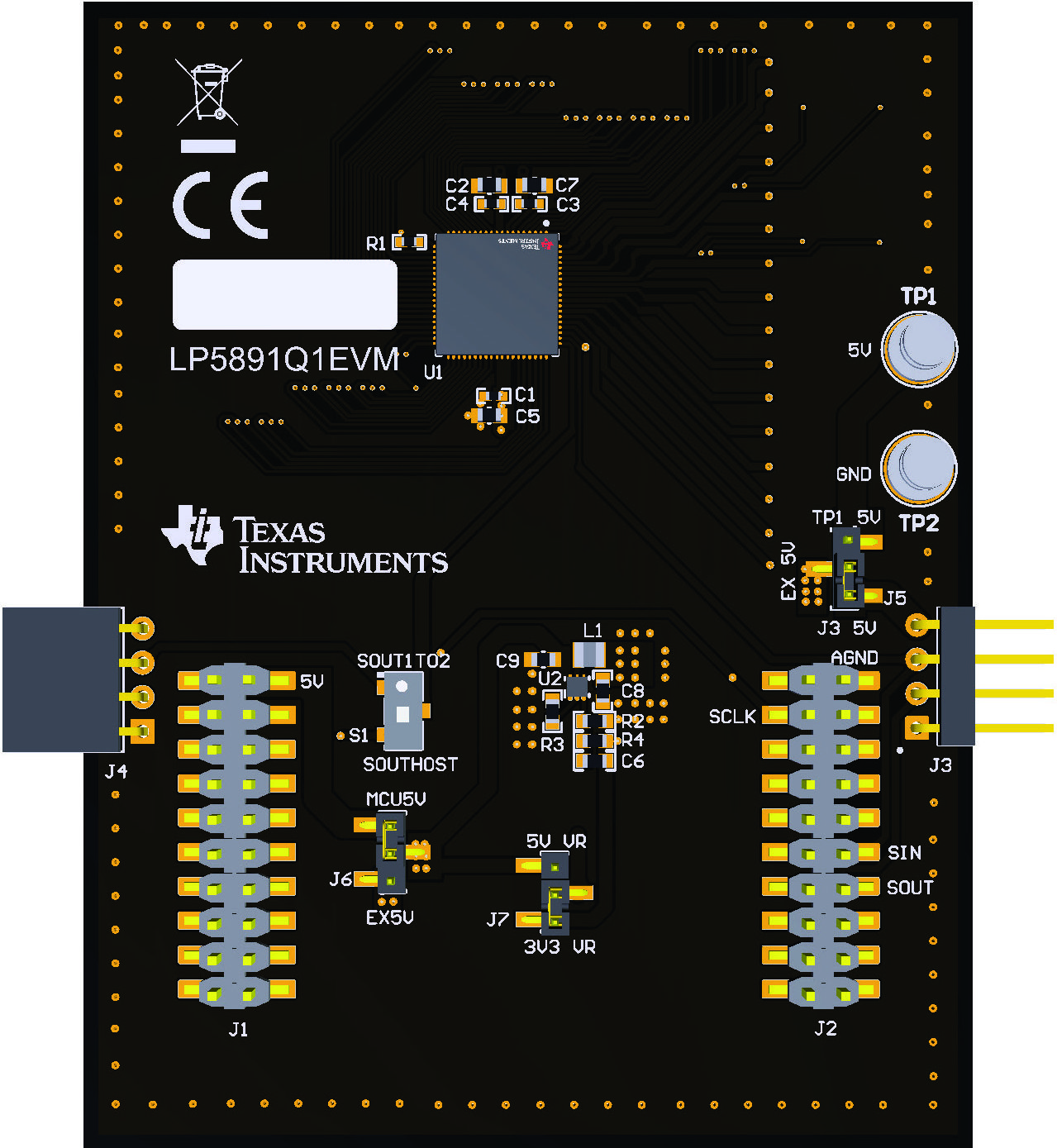
GUID-20220908-SS0I-72SP-95DC-CZHPVRX6BXNB-low.jpg Figure 2-1 Driver IC Side of the LP5891Q1EVM Board
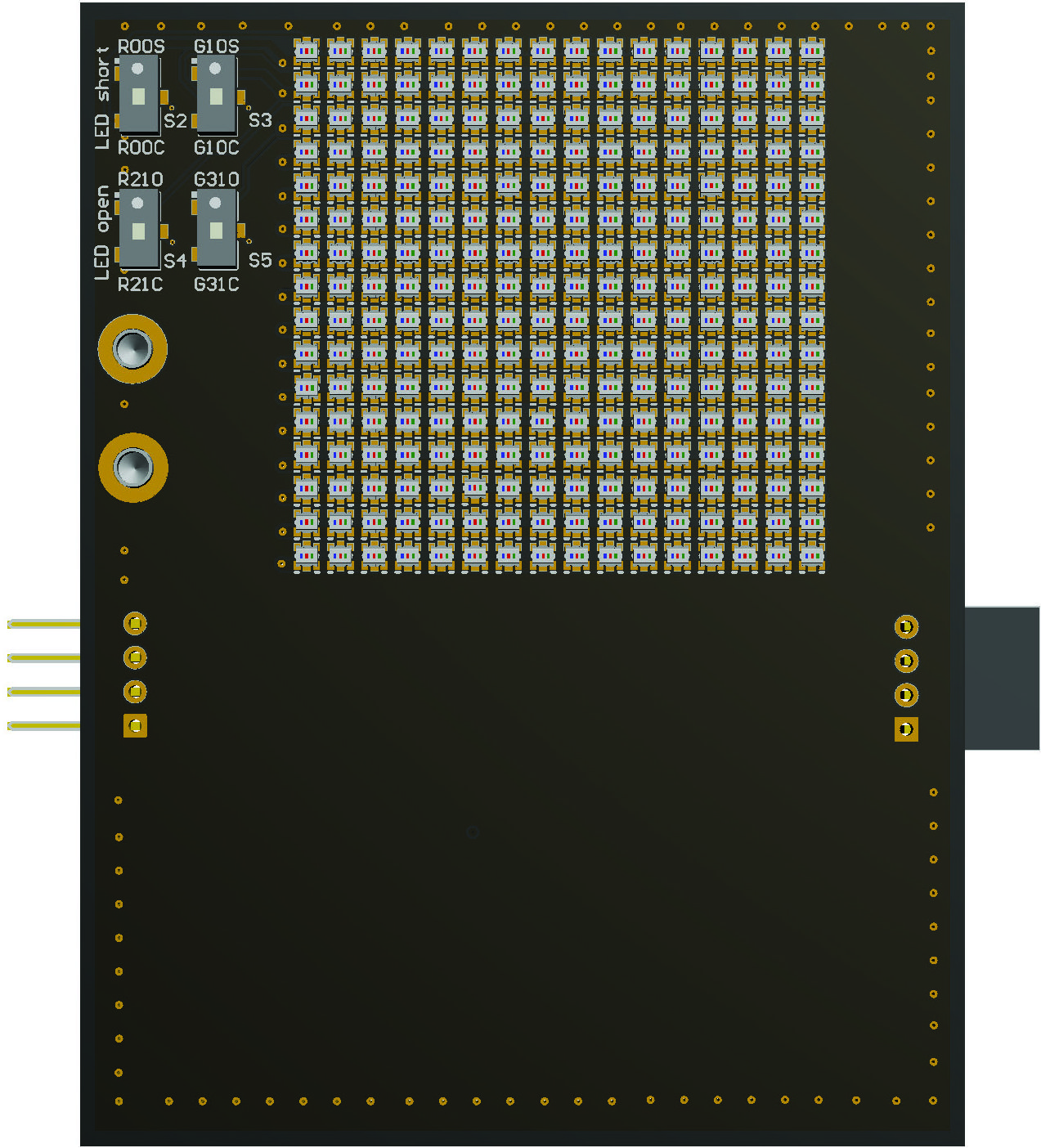
GUID-20220911-SS0I-1BDN-1FPD-7VLMG4WPDCNW-low.jpg Figure 2-2 LED Side of the LP5891Q1EVM Board

The LP5891Q1EVM works with a host controller, the TMS320F280039C LaunchPad™ for C2000™ real-time MCU. The LP5891Q1EVM is designed with connectors, jumpers, and switches to support device-to-device connection, device-to-host connection, and flexible power supply scheme. In addition, there are four switches on the LED side of the LP5891Q1EVM board that enables the evaluation of LED open and short detection and removal functions of the LP5891-Q1.

Table 3-1 lists the connectors of LP5891Q1EVM board and the descriptions.

Table 3-2 lists the jumpers of LP5891Q1EVM board and the descriptions.

Table 3-2 lists the switches of LP5891Q1EVM board and the descriptions.

Table 2-1 Connectors
Name Description
J1, J2 Boosterpack connectors for connecting with the TMS320F280039C LaunchPad.

J3

Input board-to-board connectors between LP5891Q1EVM boards, including +5V, SIN (serial data input), SCLK (serial clock), and GND.

J4

Output board-to-board connectors between LP5891Q1EVM boards, including +5V, SOUT (serial data output), SCLK (serial clock), and GND.

TP1 (+5V)

External power supply that can be selected for VLEDG/VLEDB and DC/DC.
TP2 (GND) Supply ground.
Table 2-2 Jumpers
Name Description

J3

J3 is used to select external +5V power supply.
  • Put the jumper on TP1 5V and EX 5V to select the external power supply from TP1.
  • Put the jumper on J3 5V and EX 5V to select the external power supply from J3.

J6

J3 is used to select the +5V power supply that supplies VLEDG/VLEDB and DC/DC.
  • Put the jumper on MCU5V and the middle to select the +5V power supply from the host controller.
  • Put the jumper on EX5V and the middle to select the external +5V power supply, which is previously selected by J3.

J7

J7 is used to select the power supply that supplies VLEDR.
  • Put the jumper on 5V VR and the middle to select +5V power supply for VLEDR. The +5V power supply is previously selected by J6.
  • Put the jumper on 3V3 VR and the middle to select +3.3V power supply for VLEDR. The +3.3V power supply is generated by DC/DC.
Table 2-3 Switches
Name Description

S1

  • If the switch is set towards SOUTHOST, then the serial data output from LP5891-Q1 chip is sent back to the host controller.
  • If the switch is set towards SOUT1TO2, then the serial data output from the first LP5891-Q1 chip is sent to J4 port, which is further sent to the second chip if several LP5891Q1EVM are cascaded.

S2

  • If the switch is set towards R00C, then the red LED in row 0, column 0 is connected in normal state.
  • If the switch is set towards R00S, then the red LED in row 0, column 0 is shorted (the anode and the cathode of the LED are shorted).

S3

  • If the switch is set towards G10C, then the green LED in row 1, column 0 is connected in normal state.
  • If the switch is set towards G10S, then the green LED in row 1, column 0 is shorted (the anode and the cathode of the LED are shorted).

S4

  • If the switch is set towards R21C, then the red LED in row 2, column 1 is connected in normal state.
  • If the switch is set towards R21O, then the red LED in row 2, column 1 is opened (the anode of the LED is disconnected from the current source channel).

S5

  • If the switch is set towards G31C, then the green LED in row 3, column 1 is connected in normal state.
  • If the switch is set towards G31O, then the green LED in row 3, column 1 is opened (the anode of the LED is disconnected from the current source channel).