SNVU868A September   2023  – April 2024


  1.   1
  2.   Description
  3.   Get Started
  4.   Features
  5.   Applications
  6.   6
  7. 1Evaluation Module Overview
    1. 1.1 Introduction
    2. 1.2 Kit Contents
    3. 1.3 Specification
    4. 1.4 Device Information
  8. 2Hardware
    1. 2.1 Setup
    2. 2.2 Jumper Information
    3. 2.3 Power Supply
  9. 3Software
    1. 3.1 Software Description
    2. 3.2 GUI Installation
    3. 3.3 Graphical User Interface (GUI) Guidance
  10. 4Hardware Design Files
    1. 4.1 Schematics
    2. 4.2 PCB Layouts
    3. 4.3 Bill of Materials (BOM)
  11. 5Additional Information
    1. 5.1 Trademarks
  12. 6Revision History

Schematics

Figure 5-1 shows the schematic of LED driver module.
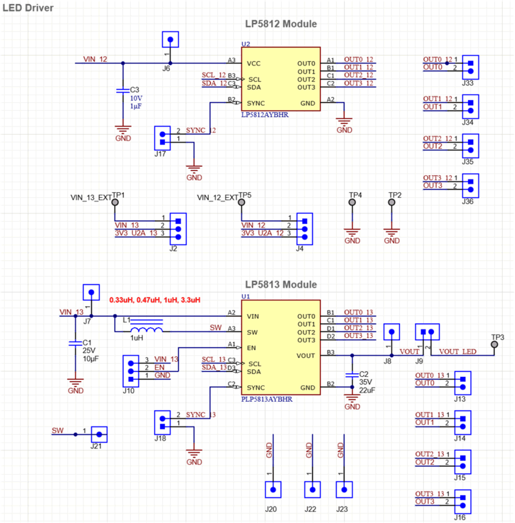
GUID-20230801-SS0I-S4RT-4HGP-8MH5TMBDK46G-low.png Figure 4-1 Schematic of LED Driver Module

Figure 5-2 shows the schematic of LED Load module.
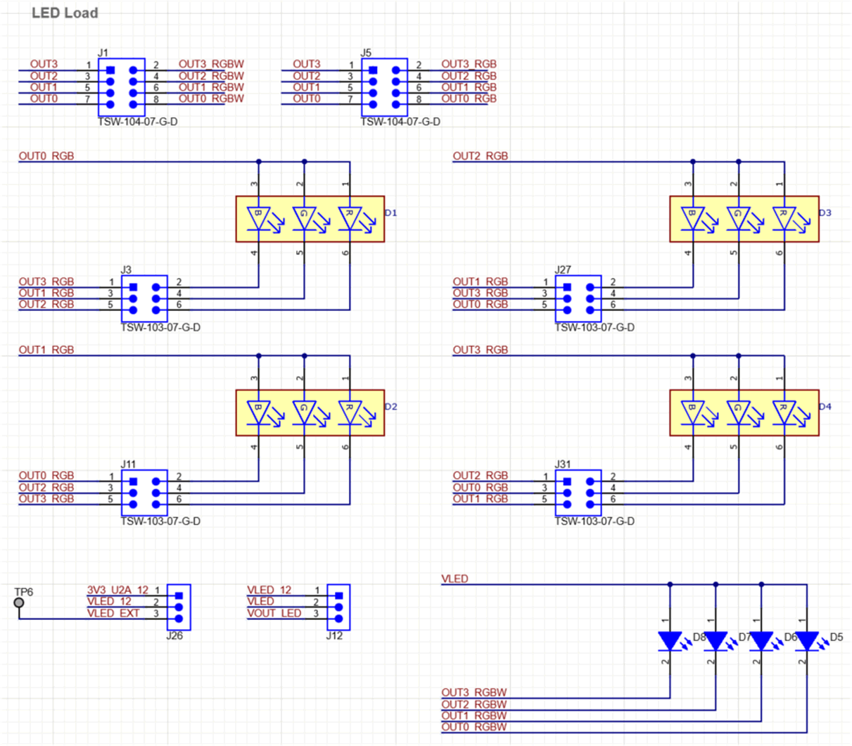
GUID-20230801-SS0I-CSHT-VHFF-PD0LBJG7QJMS-low.png Figure 4-2 Schematic of LED Load Module

Figure 5-3 shows the schematic of USB2ANY connector.
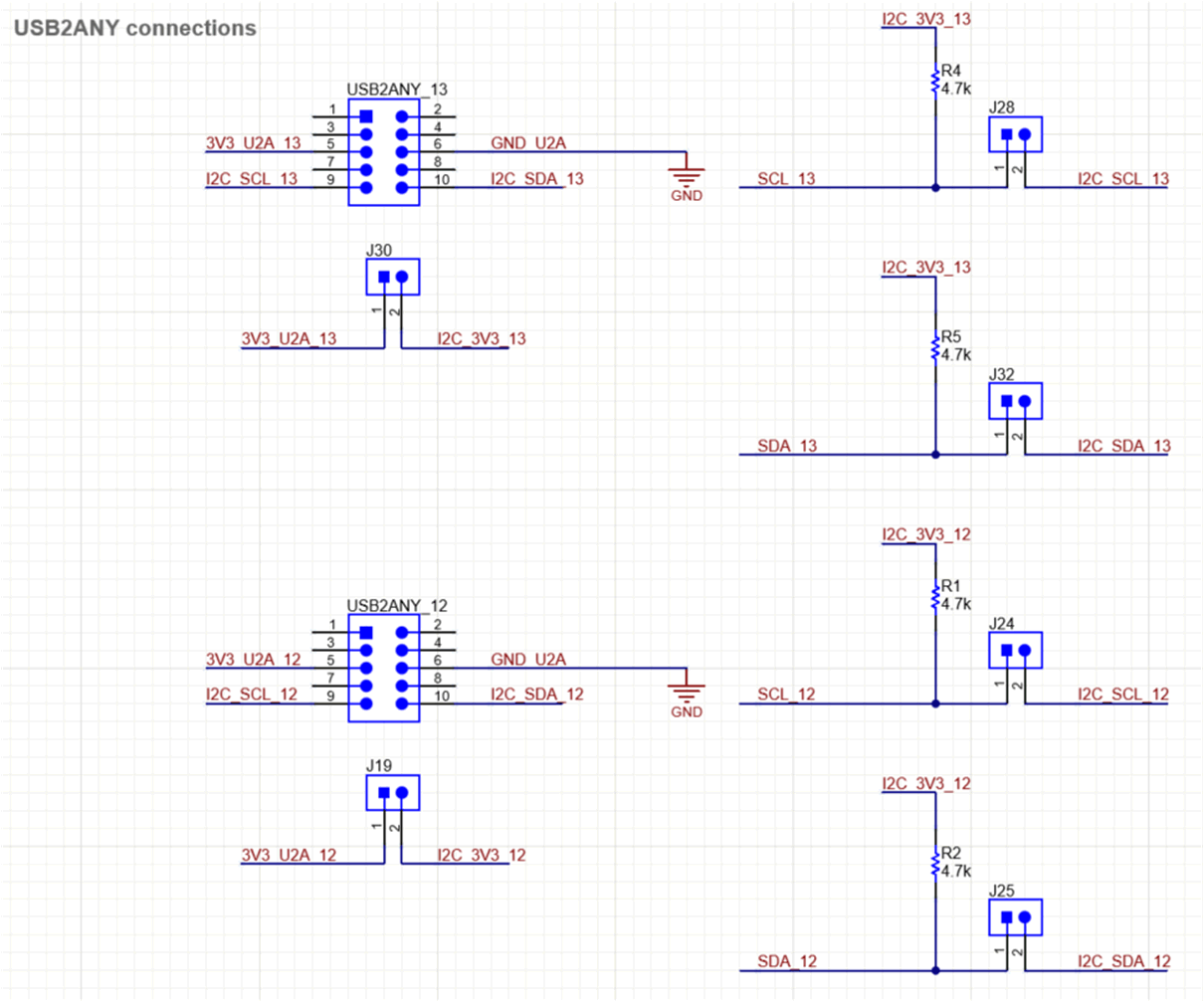
GUID-20230801-SS0I-XZTQ-VRCH-QXTTNCLGQ66H-low.png Figure 4-3 Schematic of USB2ANY Connector