SNVU871 june 2023
2.1 Hardware Setup
In the default jumper setting, the board can be evaluated by USB power directly and does not need an external power supply. Setup connection is demonstrated in Figure 2-1. The setup procedure follows:
- Connect the USB2ANY with the LP5860TEVM using the 30-pin ribbon cable.
- Plug the USB cable into the USB port on the computer.
 Figure 2-1 Hardware Connection
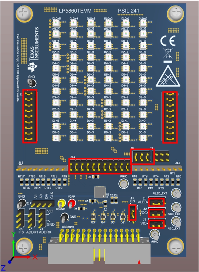
Figure 2-2 shows the default jumper settings.
 Figure 2-2 Default Jumper Setting
If maximum current is set above 20 mA, an external VLED supply is recommended during evaluation, since the USB can only provide around 400-mA current. The setup procedure follows:
- Connect the USB2ANY to the LP5860TEVM using the 30-pin ribbon cable.
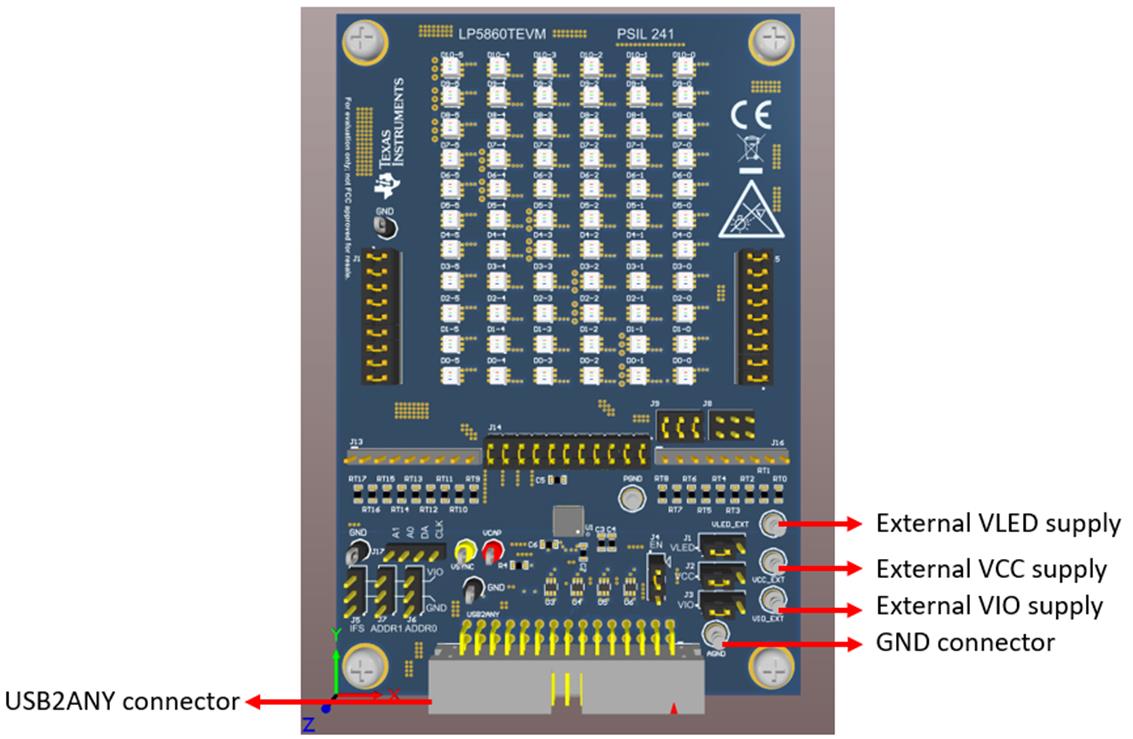
- Connect a 5-V external power supply to the VLED_EXT terminal (see Figure 2-3) and connect the switching jumper (J1) to another side.
- Plug the USB cable into the USB port on the computer.
 Figure 2-3 Key External Connectors