SPNA245 September 2020 TM4C1290NCPDT , TM4C1290NCPDT , TM4C1290NCZAD , TM4C1290NCZAD , TM4C1292NCPDT , TM4C1292NCPDT , TM4C1292NCZAD , TM4C1292NCZAD , TM4C1294KCPDT , TM4C1294KCPDT , TM4C1294NCPDT , TM4C1294NCPDT , TM4C1294NCZAD , TM4C1294NCZAD , TM4C1297NCZAD , TM4C1297NCZAD , TM4C1299KCZAD , TM4C1299KCZAD , TM4C1299NCZAD , TM4C1299NCZAD , TM4C129CNCPDT , TM4C129CNCPDT , TM4C129CNCZAD , TM4C129CNCZAD , TM4C129DNCPDT , TM4C129DNCPDT , TM4C129DNCZAD , TM4C129DNCZAD , TM4C129EKCPDT , TM4C129EKCPDT , TM4C129ENCPDT , TM4C129ENCPDT , TM4C129ENCZAD , TM4C129ENCZAD , TM4C129LNCZAD , TM4C129LNCZAD , TM4C129XKCZAD , TM4C129XKCZAD , TM4C129XNCZAD , TM4C129XNCZAD
2 Installation of Edde Flex CAN Booster Pack for TI TIVA C
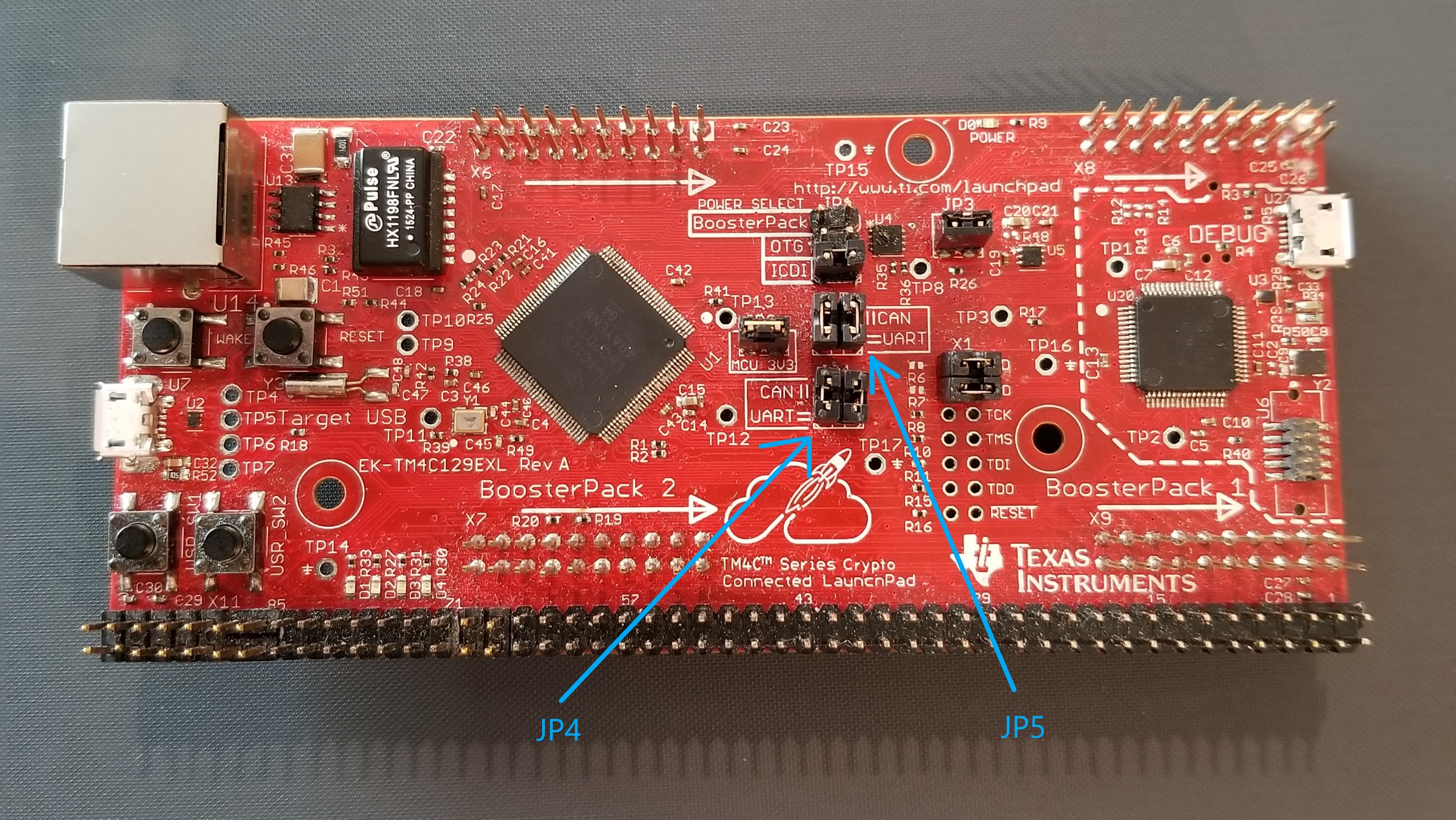
Installation of the Edde Flex CAN booster pack on the EK-TM4C1294XL or EK-TM4C129EXL Launchpad is straight forward. The first step is to put the jumpers for JP4 and JP5 in the vertical position as shown in Figure 2-1.
 Figure 2-1 EK-TM4C1294XL Jumper Position for
CAN
Figure 2-1 EK-TM4C1294XL Jumper Position for
CANIn this position, the CAN0RX (PA0) and CAN0TX (PA1) are routed to the BosterPack. UART2RX (PD4) and UART2TX (PD5) are then connected to the USB virtual serial port. All of the examples in this application report use CAN0 and UART2.
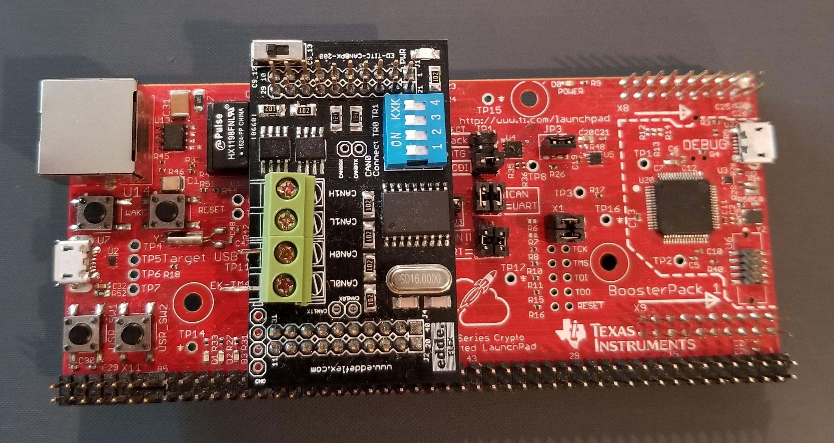
The Edde Flex BoosterPack is then placed on the BoosterPack 2 headers. Be careful to orient the BoosterPack as shown in Figure 2-2.
 Figure 2-2 EK-TM4C1294XL With Edde Flex CAN
BoosterPack
Figure 2-2 EK-TM4C1294XL With Edde Flex CAN
BoosterPackWith switches 1 and 2 in the “on” position, PA0 and PA1 are connected to the transmit and receive pins of the booster pack CAN transceiver. Switch 3 in the "on" position connects a 120 Ω termination resistor between CAN0H and CAN0L.
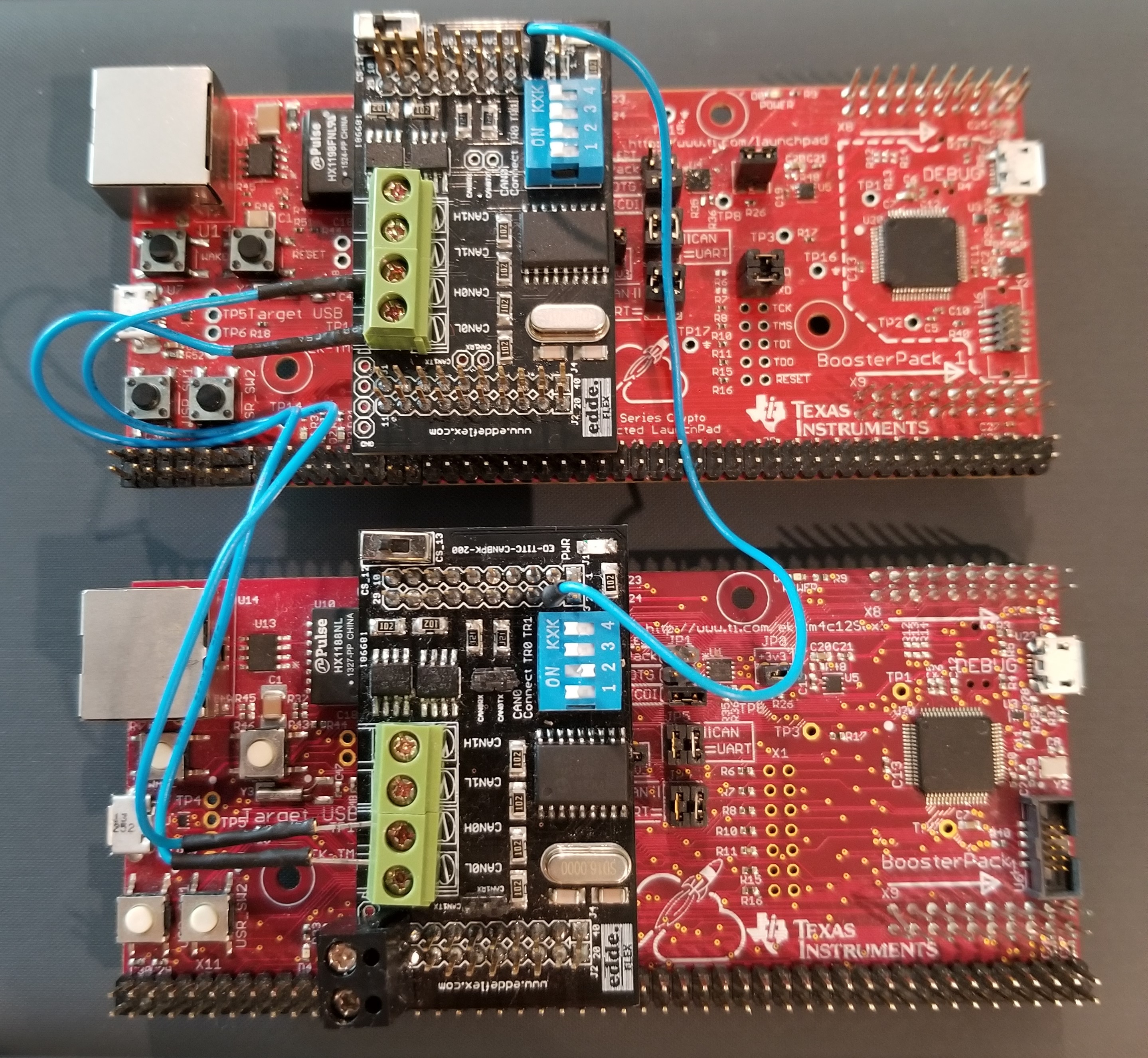
With exception to the internal loopback example, all examples require a working CAN network. A simple CAN network can be constructed using two EK-TM4C1294XL each with an Edde Flex booster pack as shown in Figure 2-3. Note that there are three connections between the two systems: CAN0H, CAN0L and GND.
 Figure 2-3 Dual EK-TM4C1294XL CAN Network