SPRUIJ3B November 2018 – April 2021
2.3 LED Lights
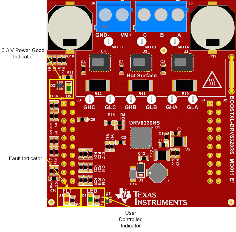
Two LEDs have been provided to indicate different statuses of the motor controller.
 Figure 2-5 Switches and LED
Functions
Figure 2-5 Switches and LED
Functions-
"FLT" and "LED" LEDs
The fault(FLT) LED is
controlled by the DRV8320's "Fault" pin. The fault pin is driven by the
DRV8320X to indicate a wide variety of warning and error conditions.
Descriptions of these can be found in the DRV832x 6 to 60-V Three-Phase
Smart Gate Driver Data Sheet. The LED marked "LED" is
available for the user to control and is active low.