SPRUIT0A December 2019 – May 2020
-
Jacinto7 EVM Infotainment Expansion
- Trademarks
- 1 Introduction
- 2 Infotainment Expansion Board Overview
- 3 Infotainment Expansion Board - User Setup/Configuration
- 4
Infotainment Expansion Board Hardware Architecture
- 4.1 Infotainment Expansion Board Hardware Top Level Diagram
- 4.2 Expansion Connectors
- 4.3 Board ID EEPROM
- 4.4 Audio Codec Interface
- 4.5 FPD link De-Serializer Interface (Audio)
- 4.6 DIR Interface
- 4.7 DIT Interface
- 4.8 Legacy Audio/JAMR3 Connectors
- 4.9 VIN/VOUT Mux Selection
- 4.10 HDMI Interface Bridge
- 4.11 FPD Link Display Serializer Interface
- 4.12 Parallel Camera Interface
- A Jacinto7 EVM Interface/IO Mapping
- Revision History
4.6 DIR Interface
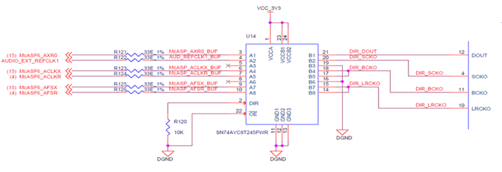
Infotainment expansion board is having a TI‘s Digital Audio Interface Receiver (DIR) IC Mfr. Part# DIR9001-Q1 to process the external digital audio input signal. The DOUT, SCKO, BCKO & LRCKO Outputs of DIR IC is connected to CP Board McASP signals Using a MUX/DMUX IC U14 Mfr. Part# SN74AVC8T245PWR and U17 IC Mfr. Part# SN74CB3Q3257PWR on INFO Board.
 Figure 13. DIR 1:2 DeMux
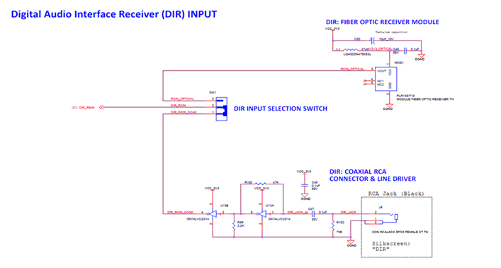
 RCA Jack Mfr. Part# RCJ-041 (Black) used to receive the external audio with buffer/filter circuitry. The input can be selected between DIR coaxial cable and a SPDIF optical input by using a switch (SW1).
 Figure 14. DIR Interface Selection Switch
 Table 6. DIR Interface Selection Switch
| SW1 | Input Type |
|---|---|
| 1-2 | Co-Axial RCA |
| 2-3 | Fiber Optic Receiver |