SSZT115 november 2021 LM74720-Q1 , LM74721-Q1 , LM74722-Q1
The increasing number of electronic circuits in vehicles is placing greater demand on the amount of power consumed from the battery. The battery supply remains on even when the car is parked or turned off, in order to support such features as remote key entry and security.
Since all vehicles run on a finite battery supply, it's important to find a way to add more functionality –particularly when designing automotive front-end power systems – without adding significant drain on the battery. The need to comply with stringent electromagnetic compatibility (EMC) standards such as the International Organization for Standardization's ISO7637 and the LV 124 standard, which was established by German automotive manufacturers, directly affects the overall design of front-end reverse battery protection systems. Several original equipment manufacturers specify the total current consumption when the vehicle is in a parked state at <100 µA per electronic control unit (ECU) in 12-V battery-powered systems and <500 µA in 24-V battery-powered systems.
In this article, I will review three approaches to designing a low quiescent-current (IQ) automotive reverse battery protection system.
Using a T15 as an Ignition or Wakeup Signal
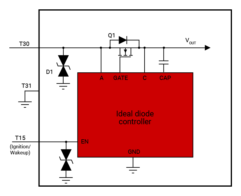
The first approach to designing a low IQ reverse battery protection system is to use a terminal 15 (T15) as an ignition or wakeup signal. The T15 is a wire terminal that disconnects from the battery when the vehicle's ignition is off. Using a T15 as an external wakeup signal is one of the most traditional ways to operate ECUs in sleep or active mode. Figure 1 shows one example.
 Figure 1 Reverse Battery Protection in
an Automotive ECU Using a T15 for Wakeup
Figure 1 Reverse Battery Protection in
an Automotive ECU Using a T15 for WakeupWhen the ignition is on, the T15 connects to the battery voltage (VBATT) potential, which drives the enable (EN) pin of the ideal diode logic high. The ideal diode controller, in active mode, while enabling the charge pump, control and field-effect transistor (FET) driver circuits, actively controls the external FET for ideal diode operation. When the vehicle is being parked, the T15 drops to 0 V, and the ideal diode controller responds by entering a shutdown state, which turns the charge pump and control blocks off, resulting in an IQ consumption of < 3 µA. In this mode of operation, the external FET turns off and the body diode of the FET forms the forward conduction path to power the load. This scheme requires an additional wiring line to the ECUs.
Using the System's MCU and CAN Wakeup Signal
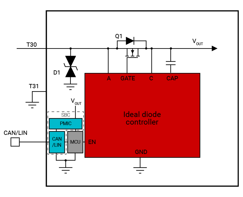
The second approach is to use the system's microcontroller (MCU) and Controller Area Network (CAN) wakeup. In many cases, the communication channels of the system make a low-IQ shutdown mode possible. Figure 2 shows an example system design using this approach.
 Figure 2 Low IQ Reverse
Battery Protection Using an MCU and CAN Wakeup Signal for Enable Control
Figure 2 Low IQ Reverse
Battery Protection Using an MCU and CAN Wakeup Signal for Enable ControlThe CAN transceivers in the vehicle translate messages from the communication bus to their respective controller – typically an MCU. The transceivers can indicate when functions are unnecessary by issuing a command to go into a standby mode until they are awakened. They then relay the message instructing the controller to place the system in a low-power state – in this case, by driving the EN signal of the ideal diode controller logic low. With more advanced transceivers and system-basis chips, one device can handle multiple functions of this process, transitioning to a low-power state or waking up.
This scheme requires an internal control signal from an MCU (via CAN control).
Using an Always-on Ideal Diode Controller
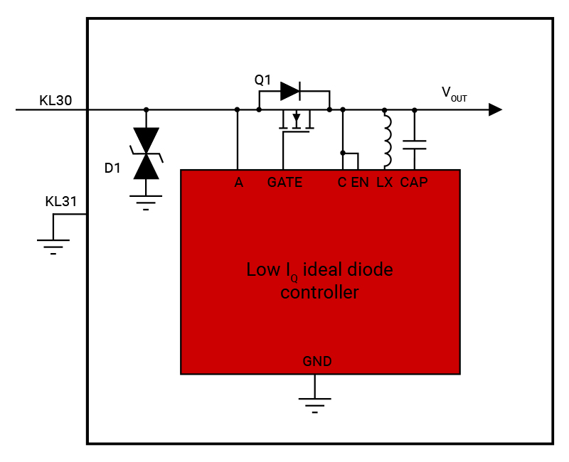
A third approach is to use an always-on ideal diode controller. Imagine a system design that does not require control signals to enter low-power states. This would eliminate the need for additional wiring or system software dependencies while allowing the ideal diode controller to always be enabled, even during sleep mode. This type of system design is possible using a low-IQ ideal diode controller such as the LM74720-Q1, LM74721-Q1 or LM74722-Q1, shown in Figure 3. These devices integrate all of the necessary control blocks for an EMC-compliant reverse battery protection design, along with a boost regulator to drive the high-side external MOSFET, which results in 27 µA of IQ during normal operation. Learn more in the application note, "Basics of Ideal Diodes."
 Figure 3 Using an Always-on
low-IQ Ideal Diode Controller without External Enable Control for
Reverse Battery Protection
Figure 3 Using an Always-on
low-IQ Ideal Diode Controller without External Enable Control for
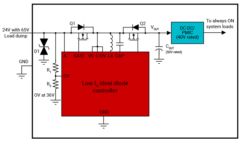
Reverse Battery ProtectionThese ideal diode controllers support reverse battery protection with active rectification and load-disconnect FET control with a back-to-back FET topology to protect the downstream during system faults such as an overvoltage event, as shown in Figure 4.
 Figure 4 Reverse Battery Protection in
a 24-v Automotive ECU Using the LM74720-Q1
Figure 4 Reverse Battery Protection in
a 24-v Automotive ECU Using the LM74720-Q1With an adjustable overvoltage protection feature, you can use 50-V-rated downstream filter capacitors (instead of 80- to 100-V-rated capacitors) and 40-V-rated DC/DC converters (instead of 65-V rated converters) for a 24-V automotive battery input-based system design.
The LM74720-Q1 and LM74721-Q1 provide fast reverse (0.45 µs) and forward comparators (1.9 µs), and a strong 30-mA boost regulator to support and enable resilient and efficient active rectification during automotive AC superimposed testing up to a 100-kHz frequency. The LM74722-Q1 offers two times faster rectification speed than the LM74720-Q1 and LM74721-Q1 devices, with a forward comparator response of 0.8 µs, enabling active rectification frequency up to 200 KHz. The LM74721-Q1 features an integrated drain-to-source voltage (VDS) clamp that enables transient voltage suppressor (TVS)-less reverse battery protection design, resulting in denser system solutions. Read more about active rectification in our application report, "Active Rectification and its Advantages in Automotive ECU Designs."
Conclusion
The LM74720-Q1, LM74721-Q1 and LM74722-Q1 low-IQ always-on ideal diode controllers enable you to design an automotive reverse battery protection system without the need for external enable control. With low IQ, back-to- back FET driving capabilities and over-voltage protection, these ideal diode controllers enable designs to use downstream components such as capacitors with lower voltage ratings, and reduce the size of printed circuit boards for space-constrained ECUs.