SSZT366 november 2019 BQ76940 , LM2904B , LM5163 , LM5164
With the rapid growth in demand for delivery services, electric motorcycles (e-motorcycles) are becoming more popular as a transportation method because the battery capacity is much larger than e-bike/e-scooter batteries. More capacity enables longer ride times, which helps save time and enables longer-distance deliveries.
An e-motorcycle battery pack has several voltage platforms, but the most popular one is 60 V, which requires 17 series (17S) lithium-ion (Li-ion) battery cells in a pack.
Generating longer run times requires addressing three design concerns:
- High cell voltage sensing accuracy for accurate state-of-charge calculations.
- Cell voltage balancing.
- Low system current consumption, especially in standby mode.
The 16S-17S Battery Pack Reference Design with Low Current Consumption addresses each design concern. It uses the BQ76940 battery monitor for the lower 15S of the pack and the LM2904B dual-channel general-purpose amplifier for accurate voltage sensing of the two upper cells. Adding external metal-oxide semiconductor field-effect transistors (MOSFETs) enables larger cell-balancing capacity. Figure 1 is a block diagram of the battery pack reference design.
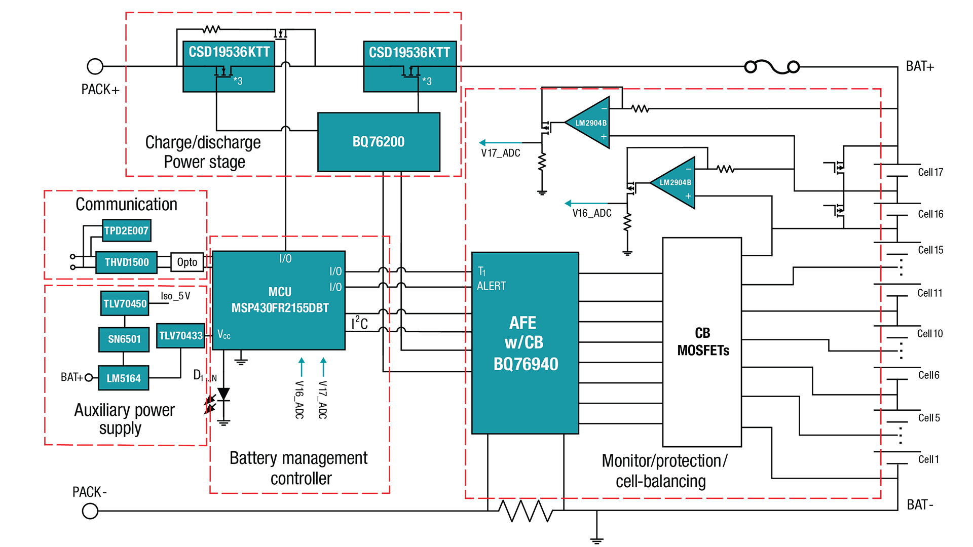 Figure 1 16S-17S Battery Pack Block
Diagram
Figure 1 16S-17S Battery Pack Block
DiagramHigh Cell Voltage Sensing Accuracy
The BQ76940 monitors the lower 15S battery cells directly and determines the cell voltage accuracy. The typical accuracy is ±15 mV at 25°C from 3.2 V to 4.6 V. Extra calibration is helpful to improve the accuracy further if necessary. The discrete circuit shown in Figure 2 determines the accuracy of the two upper cells.
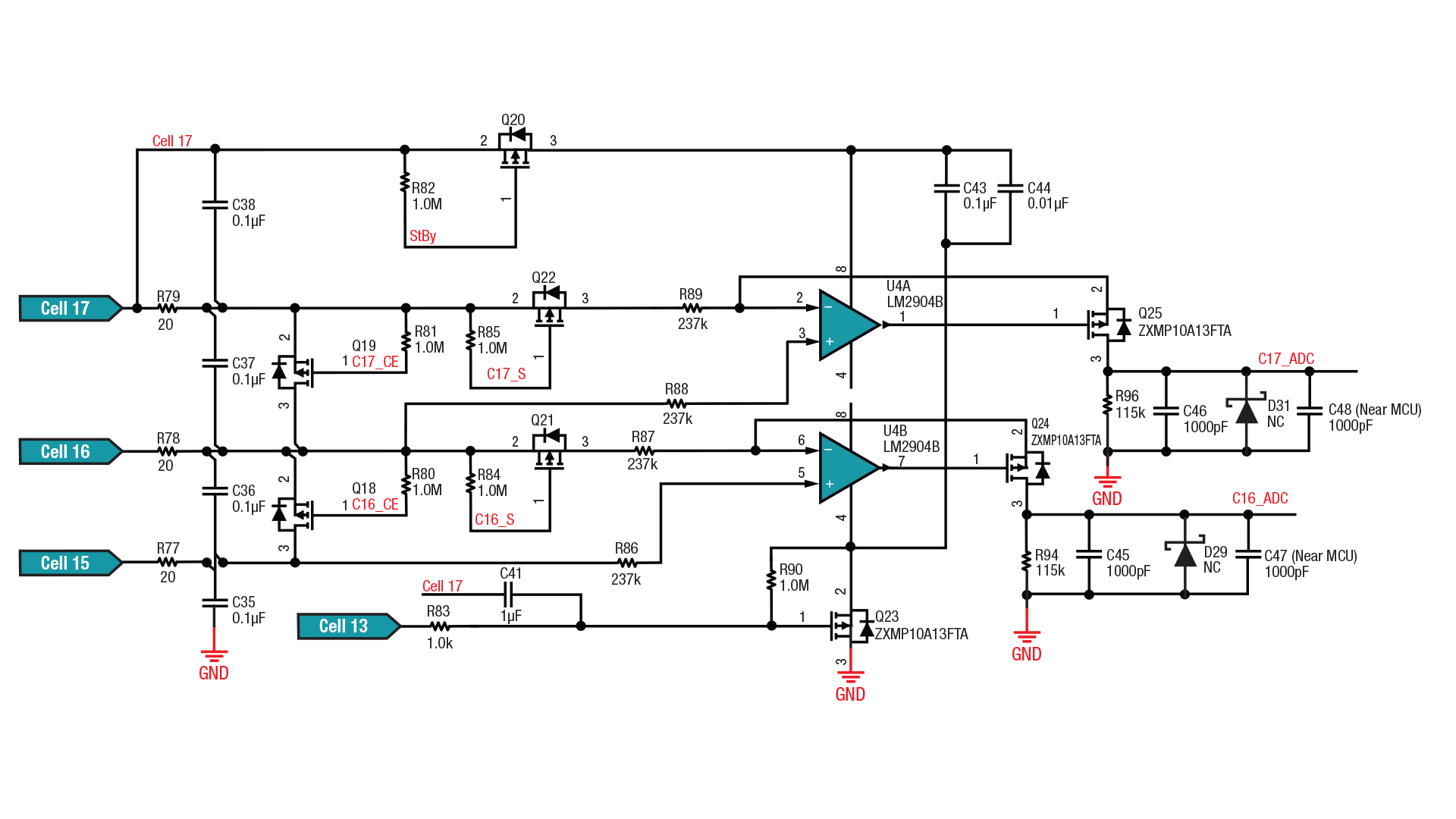 Figure 2 Diagram of the Discrete Circuits for the Two Upper Cells
Let’s take the 17th cell as an example. One LM2904B channel works together with P-channel MOSFET Q25, R89 and R96 as a negative feedback circuit while Q25 works in linear mode. The general-purpose amplifier’s negative input voltage is equal to the positive input voltage, which is the voltage of the 16th cell. The 17th cell voltage is across R89 and generates a current that will flow through Q25 and R96 and back to ground, similar to the 16th cell.
The 16th and 17th cell voltages can be monitored by measuring the ADC_16 and ADC_17 voltages with an analog-to-digital converter (ADC). Considering the tolerance of R89, R96, R87, R94 and the ADC reference, two-point calibration is necessary for higher accuracy. Figure 3 shows the two-point calibration process.
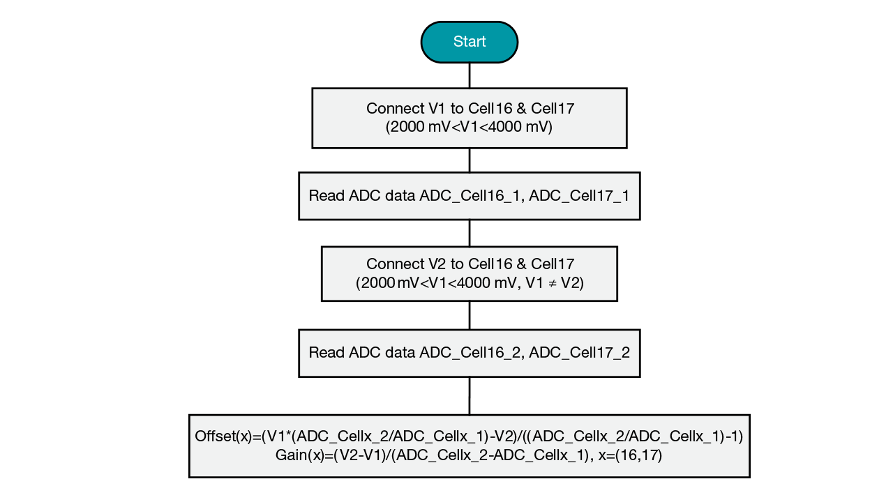 Figure 3 Two-point Calibration Process
In the lab, I tested the 16th and 17th cell voltage accuracy after calibration; the results are shown in Figure 4. The typical accuracy reaches ±2 mV.
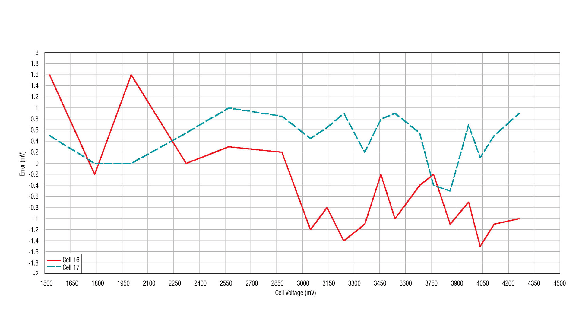 Figure 4 16th and 17th Cell Voltage Accuracy (at 25°C)
Cell Balancing
Since the 16th and 17th cells are monitored by a discrete circuit and the lower 15 cells are monitored by the BQ76940, you must consider the impact on cell balancing.
To reduce unbalancing, turn off Q21 when not sensing the 16th cell – and consider the Q21 control circuit current when calculating the unbalancing effect.
Based on the analysis here and assuming a voltage sensing period of 250 ms, the typical unbalancing current of this battery pack reference design is less than 0.1 µA.
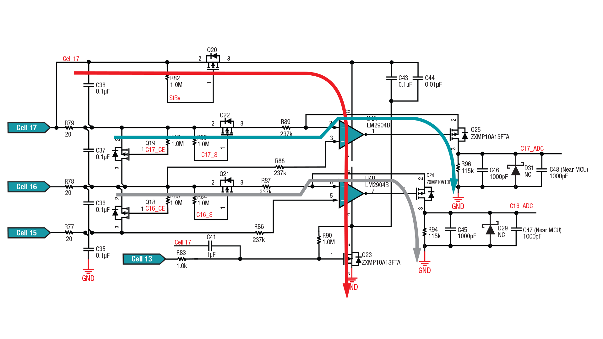 Figure 5 Diagram of the Current Paths of the Discrete Circuit
Low System Standby Current Consumption
In my previous article, “Power to the pedal: Achieving longer-lasting 13S, 48-V lithium-ion battery packs for e-bikes and e-scooters,” I explained how to reduce system-level current consumption in standby mode with the LM5164 and a system-level design. Now, I want to briefly discuss how to reduce current consumption of the discrete circuit in standby mode. There is neither charging nor discharging in standby mode. Cell voltage sensing is for protection and you can normally reduce the frequency by adding idle time. To reduce power consumption in standby mode, you can power off the circuit when voltage sensing is not required.
Conclusion
Overall, the reference design offers a cost-competitive battery pack solution that covers cells as high as 17S, which is a good fit for e-motorcycles. The design achieves longer run times by:
- Improving cell voltage sensing accuracy.
- Reducing current consumption in standby mode.
- Eliminating the unbalancing effect.
This design is also suitable for a telecom battery backup unit, which requires a 16S/48-V lithium-iron phosphate battery pack.