SSZT573 december 2018 ADS131A04 , AMC1301 , OPA4180
In my two previous blog posts on improving data acquisition (DAQ) for grid protection and control, I discussed the need for interfacing multiple analog-to-digital converters (ADCs) to a single processor and using the programmable real-time unit subsystem and industrial communication subsystem (PRU-ICSS) to improve sensor DAQ performance. In this post, I will discuss the DAQ accuracy requirements for voltage, current and active energy used in grid applications and discuss our High Accuracy ±0.5% Current and Isolated Voltage Measurement Reference Design Using 24-Bit Delta-Sigma ADC, which is based on the ADS131A04 24-bit delta-sigma ADC.
| Moving from conventional to intelligent substations | |

|
Learn more about intelligent substations by reading our new white paper, "Moving from conventional to intelligent substations." |
Grid Protection and Measurement
The AFE shown in Figure 1 includes a sensor interface, gain scaling to the ADC range, input transient protection, analog-to-digital conversion and a host interface.
 Figure 1 DAQ Subsystems Including an AFE
Protection and Measurement Class Accuracy Requirements for Current, Voltage and Active Energy
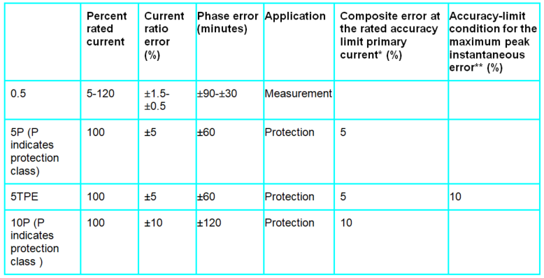
Current Transformers
CTs are used to protect equipment against overload, short-circuit and unbalance. The accuracy of protection-class CTs is low, but still high enough to sense fault currents. In protection-class CTs, the error is specified at 100% of In. Protection class CTs are specified as 5P20, meaning that at 20 times In (accuracy limit factor) the error must be <±5%. Standard accuracy-limit factors are 5, 10, 20 and 30 and P indicates protection class. Measurement class CTs has higher accuracy requirements with a limited range.
|
*The rated accuracy limit primary current is the value of the primary current up to which the protection-class CT complies with composite error accuracy requirements.
**The peak instantaneous error assesses the error of transient DC and AC components.
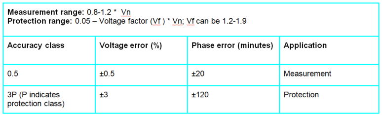
Potential Transformers
|
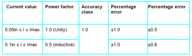
Power and Energy
|
Our reference design for current and isolated voltage measurement shows how to measure voltage, current and energy with high accuracy over a wide input range and has the functional blocks as shown in Figure 2.
 Figure 2 Reference Design AFE Block Diagram
The key functions of the AFE are:
- Isolated voltage input: An onboard resistor divider scales input voltages to 0-175 mV rms for measurement using the AMC1301 isolation amplifier with ±250-mV input and a differential output with 8.2 gain.
- Isolated power: A transformer driver and low-dropout regulator generate the required isolated supply.
- Non-isolated voltage input: An onboard resistor divider scales input voltages to 0-1,000 mV rms for measurement along with a gain amplifier.
- Current input: You can connect an external CT to an onboard burden resistor with gain amplifiers to measure the current inputs.
- Gain amplifier: A scalable fixed-gain operational amplifier scales the inputs to the ADC range.
- ADC and host interface: The output of the gain amplifiers are interfaced to the ADS131A04 24-bit delta-sigma four-channel simultaneous-sampling ADC, with an input range of ±2.5 V and a configurable reference of 2.44 V or 4 V depending on the signal input range. The ADC interfaces to the host using Serial Peripheral Interface.
- Temperature sensor: to compensate for temperature-related accuracy drift.
In the reference design, two ADCs are chained and a common clock with clock buffer is used to synchronize all channels. Chaining of two ADCs together expanded the input channel to 8 with a synchronization delay of 5-µs or less between channels.