SSZT704 may 2018
Photographers will always have the artistic license to claim that motion blur was their intention. But machine vision use cases such as imaging-based automatic inspection, quality control and code reading in factory automation and logistics require ultimate sharpness of any acquired images.
Machine Vision – Not a Task for Still Life Photographers
It’s not a question whether there is motion or not; there is only the question about the speed (v) of the motion and the challenge of capturing an image with the sharpness required.
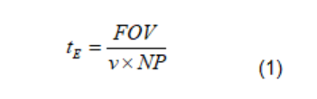
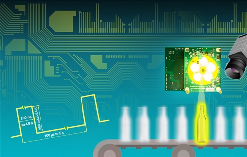
where tE is the necessary exposure time to achieve one pixel of blur for a given size of the field of view (FOV) and number of pixels (NP). FOV and NP are both in the direction of motion of the object’s speed of motion (v), see Figure 1.
 Figure 1 Typical Setup for a Machine
Vision System: Short Strobe Pulses Freeze the Motion of the Objects on the
Conveyor Belt
Figure 1 Typical Setup for a Machine
Vision System: Short Strobe Pulses Freeze the Motion of the Objects on the
Conveyor BeltLet’s establish an example:
- FOV = 12.8mm.
- Need to take an image of a 10mm object.
- v = 3 meters per second is the speed of the conveyor belt.
- NP = 1280, based on a 1280-by-1024 pixel resolution of the image sensor.
Plugging these values into Equation 1 gives you:
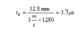
It’s now up to you to find a way to generate a light pulse (strobe) with a tE equal to or less than 3.µs. Keep in mind some applications may require a shorter exposure time due to a higher speed of the moving object.
At TI, we started brainstorming a design to nail down a specification and ended up with a documented hardware sample. At the top of our wish list was the ability to drive light-emitting diodes (LEDs) with strobe durations down to 1 µs. The LEDs had to be driven with a programmable closed-loop controlled constant current. We also wanted some nice-to-have features, like support for high frame rates, a wide input-voltage range and a trigger interface. We ended up with the LED Lighting Control Reference Design for Machine Vision, shown in Figure 2.
 Figure 2 LED-lighting Control Reference
Design for Machine Vision with the LEDs Switched on
Figure 2 LED-lighting Control Reference
Design for Machine Vision with the LEDs Switched onThe LED-lighting control reference design features:
- The ability to drive a string of five high-power LEDs.
- LED currents from 200 mA to 2.4 A.
- Up to 40 W of pulse power.
- Continuous or strobed operation of the LEDs.
- Strobe duration as short as 200 ns and frame rates up to 10 kHz.
- A wide 8 V to 36 V power input with a 15 W input power limit.
- Galvanically isolated trigger- and UART-interface.
- An isolated low-power 5 V rail for external use.
The reference design is divided into sub-blocks representing the different functions. We implemented some uncommon approaches to achieve this complete feature set, which I discuss in this post.