SSZT932 october 2017 LM73605
In this blog post, I’d like to discuss a methodology for providing a variable output voltage in an inverting buck-boost topology. In this topology, the choice of resistors on the feedback voltage divider network defines the output voltage, as shown in Figure 1.
 Figure 1 Configuration of an Inverting
Buck-boost Converter
Figure 1 Configuration of an Inverting
Buck-boost ConverterFor a different output voltage, you will need to use a different set of resistor values. This may turn out to be a tedious process if the output voltage changes constantly. So let’s discuss a method of current injection that you can use to obtain variable output voltages, without changing the resistor values.
As the name suggests, the current-injection method injects a small current in the feedback divider network to alter the drop occurring across the top feedback resistor, which in turn affects the output voltage. The easiest way to inject current is to use a power supply with a resistor in series, as shown in Figure 2.
 Figure 2 Current-injection Method Using
an External Supply
Figure 2 Current-injection Method Using
an External SupplyIf you connect the power supply directly to the feedback divider (without a resistor), the feedback voltage will clamp to a value dictated by the power supply. This is an undesirable situation, because if the clamped voltage is different than the reference voltage of the internal error amplifier, the device will completely turn off, if the clamped voltage is higher than the reference voltage. Or it will remain on continuously, if the clamped voltage is lower than the reference voltage, which can damage the device. In Figure 2, the Rctrl and RFBT are connected in parallel. For that configuration, Equation 1 expresses a linear relationship between the control voltage (Vctrl) and the output voltage (Vout):

The advantage of this method is the ease of implementation; however, it comes with a few disadvantages:
- Resistor value selection is difficult, as the three resistors need to be accurate in order to obtain the determined value of the output voltage. A disconnection of the external power supply (plugged out) will disturb the feedback network due to the change in resistor values, and you may not achieve the desired output voltage.
- The feedback node will be at a negative potential and the input of the power supply will be at a positive potential. Also, the positive node of the power supply will be referenced to AC ground. This may cause some instability in the circuit and the design.
- The configuration will not provide any isolation between the feedback network and the power supply. If the power supply is connected with reverse polarity, it will set Rctrl and RFBB in parallel, in turn affecting the output voltage.
To overcome these disadvantages, consider another configuration, shown in Figure 3, with a slight variation to the first method. This second method uses a p-channel n-channel p-channel (PNP) transistor along with the resistor.
 Figure 3 Current-injection Method Using
a Level Shifter
Figure 3 Current-injection Method Using
a Level ShifterEquation 2 shows the relationship between the output voltage and the control voltage, which is linear in nature:
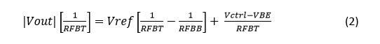
In this case, you need to calculate only the values of RFBT and RFBB in order to define the output voltage. The PNP is biased in a manner so that it operates as a constant current source. This variation in the collector voltage (that is, the feedback node) does not affect the injection current.
By using the PNP, the control voltage and feedback node are isolated from each other. Also, the high output resistance of the PNP collector does not cause any instability in the design. If the power supply is connected with reverse polarity, the PNP transistor does not turn on, offering inherent protection. The only downside to this method is that the control of the output voltage is unidirectional and needs an extra component.
Both methods have their own advantages and disadvantages. However, the method using the PNP transistor provides more robustness, along with reliable control and variation of the output voltage.
This technique of varying the output voltage in a buck-boost topology includes the 3.5V to 36V, 5A LM73605 step-down converter. TI offers a wide range of step-down converters, which you can find on the DC/DC switching regulators overview page.