SSZTC69 september 2015 SN65HVD78 , TMS320F28379D
In the first part of this blog series, I provided an overview of the various types of motor position encoders and their interfaces. In the second installment, we explained how to design an interface to a bidirectional serial synchronous (BiSS) position encoder. Now, I will introduce the EnDat 2.2 interface standard and outline how to design an electromagnetic compatible (EMC)-compliant interface to an EnDat 2.2 encoder.
The EnDat 2.2 interface from Heidenhain is a pure digital, bidirectional serial interface standard for linear or rotary position feedback encoders. The EnDat 2.2 master sends the type of data transmitted, like absolute position, parameters and diagnostics, through mode commands to the encoder. The EnDat 2.2 interface is also suited for safety-related applications up to SIL 3.
In industrial applications, the position feedback encoder might be mounted as far as 100m away from the frequency inverter. The EnDat 2.2 clock frequency is 100kHz to 16MHz for cable lengths up to 20m and up to 8MHz at 100m.
How can you design an EMC-compliant interface for a frequency inverter that meets industry standards?
IEC618000-3 specifies the EMC requirements for adjustable-speed electrical power-drive systems, where the EnDat 2.2 master interface module is a subsystem. Since the encoder cable can be as long as 100m, the interface has to pass at least the test requirements listed in Figure 1.
 Figure 1 Excerpt of IEC61800-3 EMC
Requirements
Figure 1 Excerpt of IEC61800-3 EMC
Requirements
- (A) The module shall continue to operate as intended. No loss of function or performance even during the test.
- (B) Temporary degradation of performance is accepted. After the test, the module shall continue to operate as intended without manual intervention.
- (C) During the test, loss of functions accepted, but no destruction of hardware or software. After the test, the module shall continue to operate as intended automatically, after manual restart, power off or power on.
Figure 2 is the corresponding block diagram of an EnDat 2.2 master interface module as part of a frequency inverter.
The EnDat 2.2 position encoder is connected to the EnDat 2.2 master interface through a single, eight-wire shielded cable. Two wires are for the encoder power supply and two wires are for battery-buffering or parallel power-supply wires. The serial RS-485-based communication only requires four signal wires: two for the bidirectional differential data signals DATA+ and DATA- in half-duplex mode, and two for the differential clock signal CLOCK+ and CLOCK-.
 Figure 2 EnDat 2.2 Master Interface
Module Block Diagram
Figure 2 EnDat 2.2 Master Interface
Module Block DiagramThe major building blocks of the EnDat 2.2 master interface module are:
- The protected encoder power supply for the EnDat 2.2 encoder.
- RS-485 transceivers like SN65HVD78 for EnDat 2.2 clock and half-duplex data.
- A host processor like TI’s Sitara™ AM437x processor, which implements the EnDat 2.2 master.
The first building block, the protected encoder power supply, is designed to meet Heidenhain’s specification for an EnDat 2.2 encoder with an expanded power-supply range from 3.6V to 14V.
With the Reference Design for an Interface to a Position Encoder with EnDat 2.2 (TIDA-00172), you can realize the encoder power supply with a DC/DC buck converter, as specified in Figure 3.
 Figure 3 Encoder Power Supply Generic
Specifications
Figure 3 Encoder Power Supply Generic
SpecificationsThanks to the electronic fuse (eFuse), the design also complies with IEC 61010-1, where a secondary circuit must supply power (in this design, the DC/DC buck converter), with current or power limitation set by IEC 61010-1:2011-07, section 9.4.
The eFuse, as part of the protected encoder power supply, electronically disconnects power from the encoder in case of a fault and asserts a fault flag. Fault conditions are overvoltage, undervoltage, overpower and overcurrent. The fault flag allows the host controller to recognize a fault condition like a cable short and act accordingly. Figure 4 specifies the additional protection features implemented in the TIDA-00172 reference design.
 Figure 4 Encoder Power-supply
Protection Specification
Figure 4 Encoder Power-supply
Protection SpecificationThe second building block of the EnDat 2.2 master interface is the RS-485 interface. The minimum baud rate of the RS-485 transceiver should be at least 32Mbps to support the maximum 16MHz EnDat 2.2 clock frequency.
Figure 3 shows an EMC-compliant interface for the differential data signal, realized with the reference design. It assumes that you used shielded cables from Heidenhain to connect the EnDat 2.2 encoder.
 Figure 5 EMC-compliant Interface for
EnDat 2.2 RS-485 Differential DATA Signals
Figure 5 EMC-compliant Interface for
EnDat 2.2 RS-485 Differential DATA SignalsThe RS-485 interface offers a wide -7V to +12V common-mode voltage range. To improve immunity against electrostatic discharge (ESD), electrical fast transient (EFT) and surge, the reference design uses the SN65HVD78 RS-485 transceiver with integrated ±12kV IEC ESD protection. 10Ω pulse-proof resistors limit the clamping current, while 330pF bypass capacitors attenuate common-mode voltage transients. For further details, see the TIDA-00172 TI Design folder.
The third building block realizes the EnDat 2.2 master, which controls communication. It generates the clock signal, selects the data direction, and transmits and receives data synchronous to the clock. The clock remains high when data is neither transmitted nor received.
Figure 3 shows a position-value packet-transfer example. After two clock pulses, the EnDat 2.2 master transmits a mode command (encoder transmit position) and the slave encoder replies with the position value, start and error bits, and a 5-bit cyclic redundancy check (CRC).
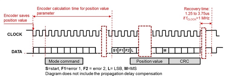
Although Figure 3 does not depict propagation delay compensation, the delay compensation is an important function, since the delay through a typical encoder cable is around 5ns/m. At a 10m cable length the round-trip delay is 100ns. With a 16MHz EnDat 2.2 clock, this equals a phase shift of 1.6 clock periods! Therefore, proper delay compensation is a major function of the EnDat 2.2 master.
The EnDat 2.2 master was implemented on FPGAs and ASICs in the past, and recently on innovative processors like the Sitara AM437x processor. The Sitara AM437x processor leverages the programmable real-time unit subsystem and industrial communication subsystem (PRU-ICSS) peripheral to implement the EnDat 2.2 master. The EnDat 2.2 master firmware is available for the Sitara AM437x processor as part of the SYS/BIOS industrial software development kit (SDK) for Sitara processors.
If you’re ready to start designing, check out the Reference Design for an Interface to a Position Encoder with EnDat 2.2 for an EMC-compliant interface and the Single Chip Drive for Industrial Communications and Motor Control for the EnDat2.2 master on Sitara AM437x.
In the next installment of this series, my colleagues and I will take a closer look at the interface to a HIPERFACE DSL® position feedback encoder.
If you would like to see this series touch on specific topics related to position encoder interface design, please post a comment below.
Additional Resources
- Learn more about the SYS/BIOS industrial software development kit for Sitara processors.
- If you are interested in the EnDat 2.2 master for C2000™ microcontrollers, check out the DesignDRIVE development kit (TMDXIDDK379D).