SSZTCJ7 june 2015 DRV8301 , TMS320F28069
I have discussed sensorless motor start-up with our InstaSPIN-FOC™ technology in part one of this series, followed by a discussion of how to generate sufficient torque at start up and maximize it while spinning your motor in part 2. In this third and final part of the series, I’ll explain how to address some challenges in applications that may have highly dynamic loads up to 100 percent or rated torque output.
Continuous Angle Tracking
To truly solve the problem, you need to be able to continuously estimate the rotor flux angle at zero and very low speeds and transition between the low-speed and high-speed observers in a stable manner. A new set of libraries is being provided to make this possible with InstaSPIN-FOC technology. The library is in two parts:
- IPD_HFI: Initial Position Detection (IPD) and High-Frequency Injection for Zero- and Low-Speed Operation
- AFSEL: Logic transitions between IPD_HFI and FAST
 Figure 1 Frequency of operation with FAST and IPD_HFI
Initial (Zero Speed) Position Detection
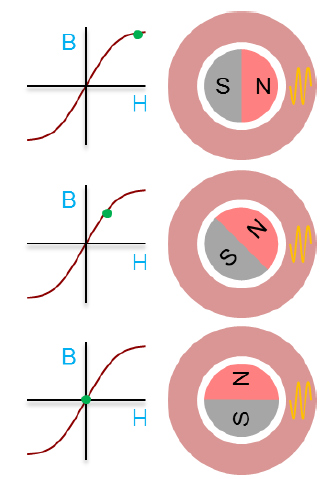
The IPD portion of the IPD_HFI module uses the BH curve of the iron that the stator coil is wrapped around to determine the north pole of the rotor and thus the d-axis. The magnetic field strength will bias the stator’s BH curve operating point as shown in in the below figure. Supporting and opposing magnetic fields are applied with the stator coil. When both fields support, the BH curve is pushed further into saturation. When the magnetic fields oppose, the BH curve operating point moves further into the linear region. The difference in inductance between these two BH curve operating points allows the IPD algorithm to determine where the rotor north pole is located.
 Figure 2 BH curve and relative location for different rotor orientations
Low Speed Position Detection
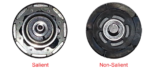
Once the rotor’s north pole is located, for best control system performance it must be tracked at all times during the operation of the motor, even the very short time between start-up and FAST reliably being able to provide valid angle estimations. The IPD_HFI solution uses a high-frequency signal to track the north pole. However, this capability relies on the motor design having a large saliency. Saliency can be introduced by placing the rotor magnets below the surface of the rotor with gaps of the rotor’s iron left in between poles. Contrast this to a non-salient surface mounted design.
 Figure 3 Salient vs. Non-Salient rotor designs
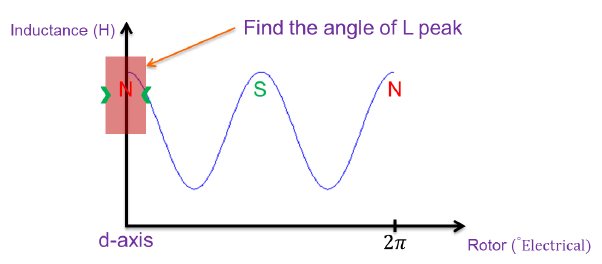
For the salient type, because the magnetic material has a much less relative permeability than the surrounding iron, the reluctance difference for flux flowing through the magnet is greater than reluctance of the iron path. As the rotor’s angle advances, the reluctance has a periodic variation. If the inductance is measured on a coil of the stator, it will look something like below:
 Figure 4 Inductance variation of a highly salient rotor
The HFI part of IPD_HFI uses this information to stay locked onto the north pole of the rotor while it is spinning at low speeds. To make certain that its angle is locked onto the north pole – and not a south pole peak – the HFI is initialized to the D-axis north pole by the IPD portion. The high-frequency signal used to excite this signature is selected based on the time constant of the motor.
Transitional Logic
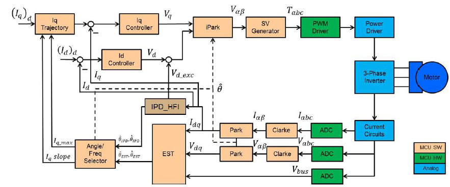
The HFI algorithm works very well at low speeds but it has a maximum speed limit. Before this maximum speed limit is reached, control has to be handed over to a higher speed observer like FAST. The module that selects between low-speed (HFI) and high-speed (FAST) estimators is the angle frequency select (AFSEL). AFSEL requires angle and frequency inputs from both the low- and high-speed estimators and the speed at which the control is passed from one estimator to the other.
 Figure 5 InstaSPIN-FOC with FAST (EST), IPD_HFI, and AFSEL
Limitations
Besides the need for a salient rotor design, one of the key limitations is the effect of the current through the motor on the saliency effect. To start a motor under load, enough current has to be consumed by the motor to produce the needed torque. As the currents increase the reluctance variation is diminished, hence the inductance variation is diminished, and the HFI portion will not estimate the angle location precisely enough to maximize torque production. This must be tested and is highly dependent on the motor design and the initial saliency (variation). More is always better.
Example Implementation
An example “Torque Control” implementation has been released as “proj_lab21” starting with MotorWare revision 1.01.00.14
Initially the project is just being released on the DRV8301 Rev D EVM inverter with our C2000™ Piccolo™ F28069 microcontroller. In future revisions of MotorWare™, support will be extended to different combinations of inverters and controllers as well as further system examples such as “Speed Control.” Learn more about InstaSPIN and IPD_HFI at www.ti.com/instaspin.