SWRA779 September 2023 CC3300 , CC3301 , CC3301MOD , CC3351MOD
5 Boot Flow
The host processor may communicate with the companion IC over either SPI or SDIO. The same hardware lines are used for the host interface where the device automatically detect the host interface mode according to a pre-defined sequence. In regards to the host interface, if a dual interface mode is used, the procedure includes a primary host interface (for Wi-Fi) and a secondary host interface (for Bluetooth Low Energy).
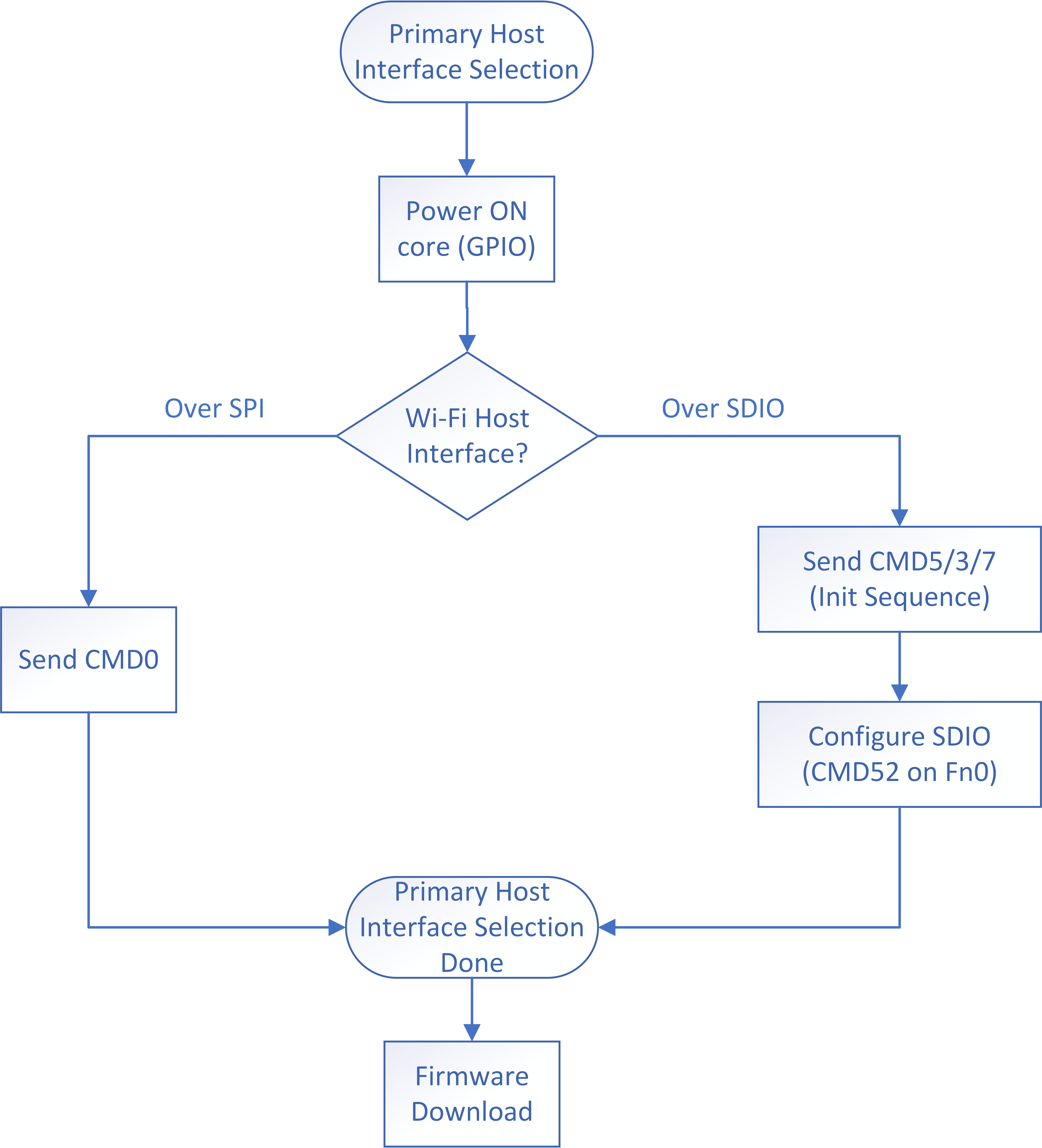
Figure 5-1 illustrates the primary interface initialization flow from the host side.
 Figure 5-1 Primary Interface
Initialization
Figure 5-1 Primary Interface
InitializationAfter the device is powered on, the host is responsible to send the correct sequence of commands. For SPI mode, a single SDIO command with opcode 0 (CMD0) is sent in order to set the device to SPI mode. For SDIO mode, the sequence includes CMD5/3/7 and then a sequence of CMD52 commands to set additional configuration parameters to the device.
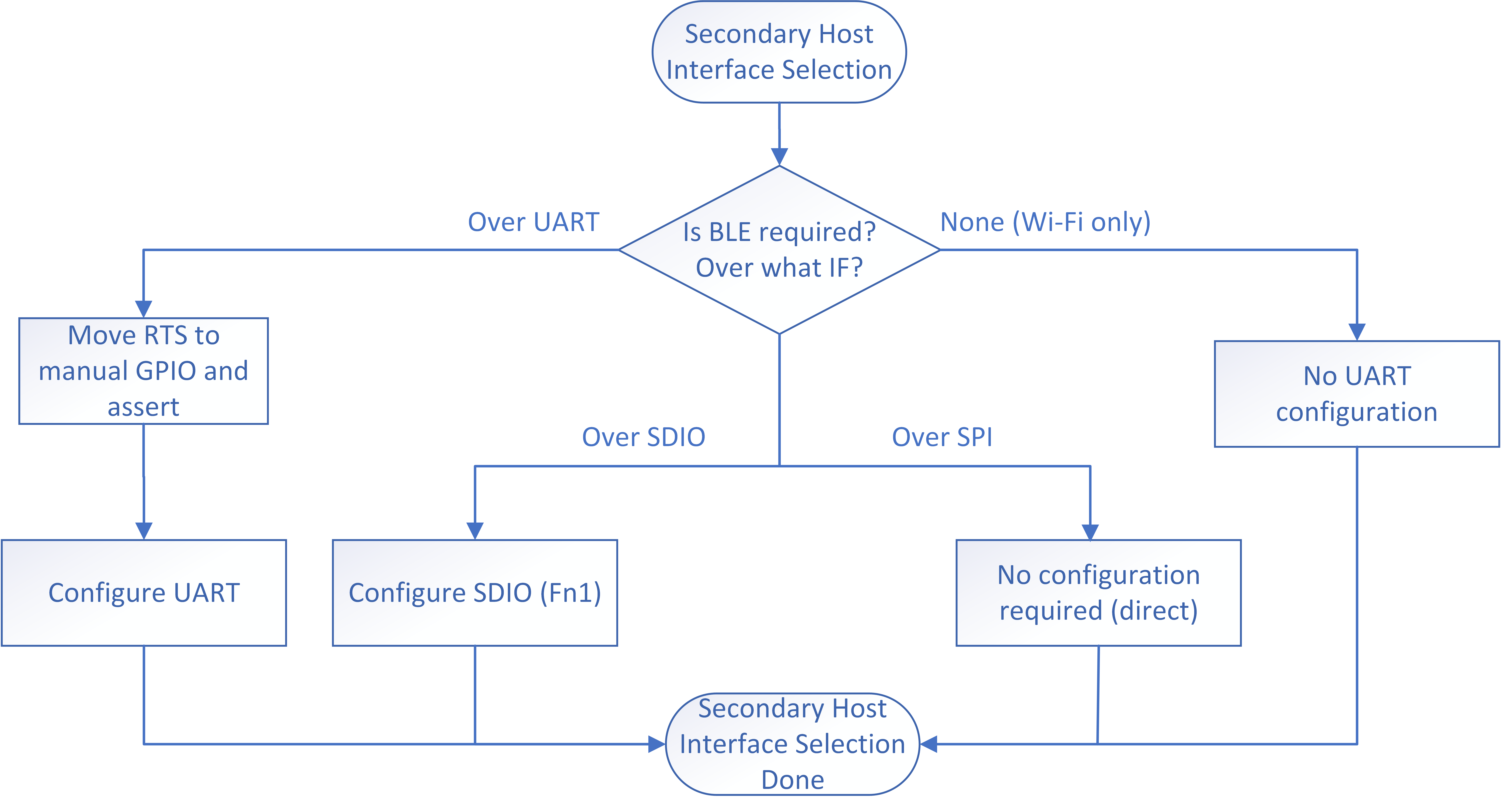
If Bluetooth Low Energy is required, a secondary interface initialization flow may be required. The Bluetooth Low Energy may be used in shared mode or in dual mode (over UART). From the device side, if UART is used then until the UART is properly configured the device shall configure the RTS line as manual controlled GPIO output and assert the RTS to further protect the Core from receiving any host commands until the UART is configured and ready. Figure 5-2 illustrates the secondary interface initialization flow from the device side.
 Figure 5-2 Secondary Interface
Initialization