TIDT232 September 2021
8 Test Setup
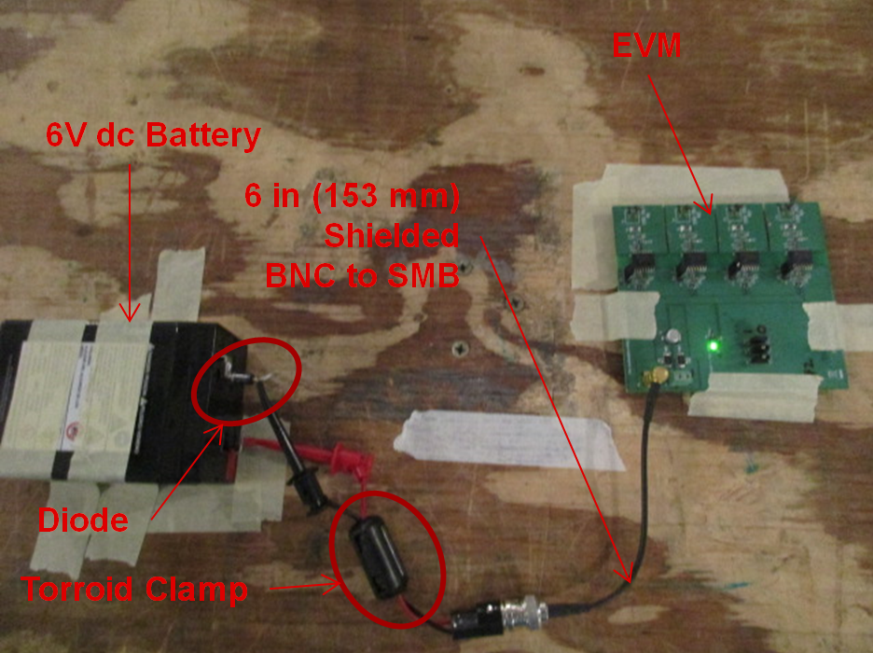
The test configuration shown in Figure 8-2 uses a 6-V, DC battery as the input voltage source to the test the EVM. For the purpose of reducing 6 V to about 5.4 V, a diode is used in series with the return connection to the DC battery. A short, shielded BNC to SMB cable is used to connect the battery to the test EVM. A toroid clamp is used to minimize the EMI effect of the cable.
 Figure 8-1 Anechoic Chamber – CISPR 32 Radiated EMI
Test
 Figure 8-2 CISPR 32 VINP Battery to EVM Test
Setup