TIDT348 august 2023
2.3 Thermal Images
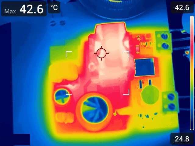
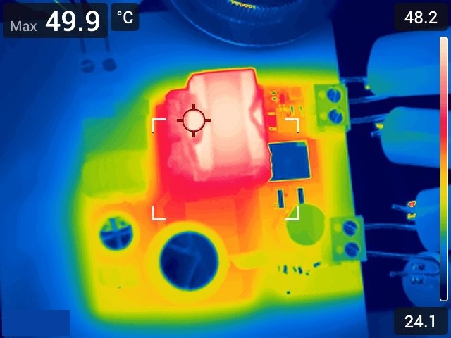
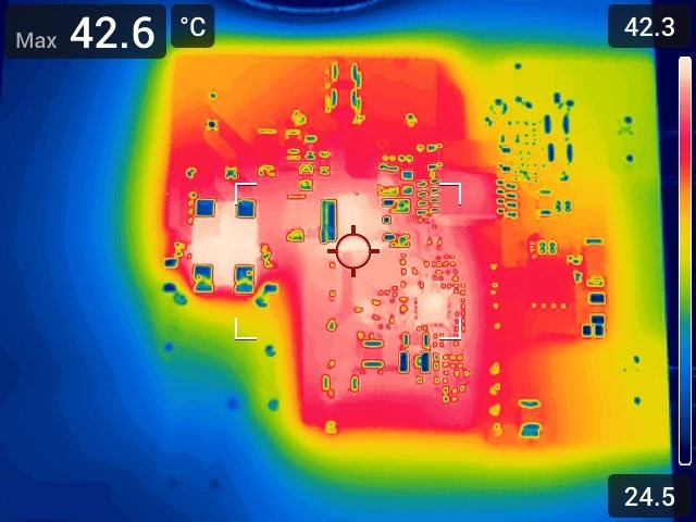
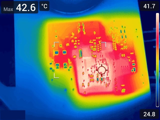
The following figures show the top and bottom thermal image of the PMP23331 at full load, taken after 20 minutes soak time, at 24°C ambient temperature and no forced airflow.
 Figure 2-3 PMP23331 Thermal Image,
115-Vac Input, Top Side
 Figure 2-5 PMP23331 Thermal Image,
230-Vac Input, Top Side
 Figure 2-4 PMP23331 Thermal Image,
115-Vac Input, Bottom Side
 Figure 2-6 PMP23331 Thermal Image,
230-Vac Input, Bottom Side