JAJSCG7 September   2016 LMK04208

PRODUCTION DATA.  

  1. 特長
  2. アプリケーション
  3. 概要
  4. 改訂履歴
  5. Pin Configuration and Functions
  6. Specifications
    1. 6.1 Absolute Maximum Ratings
    2. 6.2 ESD Ratings
    3. 6.3 Recommended Operating Conditions
    4. 6.4 Thermal Information
    5. 6.5 Electrical Characteristics
    6. 6.6 Timing Requirements
    7. 6.7 Typical Characteristics
  7. Parameter Measurement Information
    1. 7.1 Charge Pump Current Specification Definitions
      1. 7.1.1 Charge Pump Output Current Magnitude Variation Vs. Charge Pump Output Voltage
      2. 7.1.2 Charge Pump Sink Current Vs. Charge Pump Output Source Current Mismatch
      3. 7.1.3 Charge Pump Output Current Magnitude Variation vs. Ambient Temperature
    2. 7.2 Differential Voltage Measurement Terminology
  8. Detailed Description
    1. 8.1 Overview
      1. 8.1.1  System Architecture
      2. 8.1.2  PLL1 Redundant Reference Inputs (CLKin0/CLKin0* and CLKin1/CLKin1*)
      3. 8.1.3  PLL1 Tunable Crystal Support
      4. 8.1.4  VCXO/Crystal Buffered Output
      5. 8.1.5  Frequency Holdover
      6. 8.1.6  Integrated Loop Filter Poles
      7. 8.1.7  Internal VCO
      8. 8.1.8  External VCO Mode
      9. 8.1.9  Clock Distribution
        1. 8.1.9.1 CLKout DIVIDER
        2. 8.1.9.2 CLKout Delay
        3. 8.1.9.3 Programmable Output Type
        4. 8.1.9.4 Clock Output Synchronization
      10. 8.1.10 0-Delay
      11. 8.1.11 Default Startup Clocks
      12. 8.1.12 Status Pins
      13. 8.1.13 Register Readback
    2. 8.2 Functional Block Diagram
    3. 8.3 Feature Description
      1. 8.3.1 Inputs / Outputs
        1. 8.3.1.1 PLL1 Reference Inputs (CLKin0 and CLKin1)
        2. 8.3.1.2 PLL2 OSCin / OSCin* Port
        3. 8.3.1.3 Crystal Oscillator
      2. 8.3.2 Input Clock Switching
        1. 8.3.2.1 Input Clock Switching - Manual Mode
        2. 8.3.2.2 Input Clock Switching - Pin Select Mode
          1. 8.3.2.2.1 Pin Select Mode and Host
          2. 8.3.2.2.2 Switch Event without Holdover
          3. 8.3.2.2.3 Switch Event with Holdover
        3. 8.3.2.3 Input Clock Switching - Automatic Mode
          1. 8.3.2.3.1 Starting Active Clock
          2. 8.3.2.3.2 Clock Switch Event: PLL1 DLD
          3. 8.3.2.3.3 Clock Switch Event: PLL1 Vtune Rail
          4. 8.3.2.3.4 Clock Switch Event with Holdover
        4. 8.3.2.4 Input Clock Switching - Automatic Mode with Pin Select
          1. 8.3.2.4.1 Starting Active Clock
          2. 8.3.2.4.2 Clock Switch Event: PLL1 DLD
          3. 8.3.2.4.3 Clock Switch Event: PLL1 Vtune Rail
          4. 8.3.2.4.4 Clock Switch Event with Holdover
      3. 8.3.3 Holdover Mode
        1. 8.3.3.1 Enable Holdover
        2. 8.3.3.2 Entering Holdover
        3. 8.3.3.3 During Holdover
        4. 8.3.3.4 Exiting Holdover
        5. 8.3.3.5 Holdover Frequency Accuracy and DAC Performance
        6. 8.3.3.6 Holdover Mode - Automatic Exit of Holdover
      4. 8.3.4 PLLs
        1. 8.3.4.1 PLL1
        2. 8.3.4.2 PLL2
          1. 8.3.4.2.1 PLL2 Frequency Doubler
        3. 8.3.4.3 Digital Lock Detect
      5. 8.3.5 Status Pins
        1. 8.3.5.1 Logic Low
        2. 8.3.5.2 Digital Lock Detect
        3. 8.3.5.3 Holdover Status
        4. 8.3.5.4 DAC
        5. 8.3.5.5 PLL Divider Outputs
        6. 8.3.5.6 CLKinX_LOS
        7. 8.3.5.7 CLKinX Selected
        8. 8.3.5.8 MICROWIRE Readback
      6. 8.3.6 VCO
      7. 8.3.7 Clock Distribution
        1. 8.3.7.1 Fixed Digital Delay
        2. 8.3.7.2 Fixed Digital Delay - Example
        3. 8.3.7.3 Clock Output Synchronization (SYNC)
          1. 8.3.7.3.1 Effect of SYNC
          2. 8.3.7.3.2 Methods of Generating SYNC
          3. 8.3.7.3.3 Avoiding Clock Output Interruption Due to Sync
          4. 8.3.7.3.4 SYNC Timing
        4. 8.3.7.4 Dynamically Programming Digital Delay
          1. 8.3.7.4.1 Absolute vs. Relative Dynamic Digital Delay
          2. 8.3.7.4.2 Dynamic Digital Delay and 0-Delay Mode
          3. 8.3.7.4.3 SYNC and Minimum Step Size
          4. 8.3.7.4.4 Programming Overview
          5. 8.3.7.4.5 Internal Dynamic Digital Delay Timing
          6. 8.3.7.4.6 Other Timing Requirements
        5. 8.3.7.5 Absolute Dynamic Digital Delay
          1. 8.3.7.5.1 Absolute Dynamic Digital Delay - Example
        6. 8.3.7.6 Relative Dynamic Digital Delay
          1. 8.3.7.6.1 Relative Dynamic Digital Delay - Example
      8. 8.3.8 0-Delay Mode
    4. 8.4 Device Functional Modes
      1. 8.4.1 Mode Selection
      2. 8.4.2 Operating Modes
        1. 8.4.2.1 Dual PLL
        2. 8.4.2.2 0-Delay Dual PLL
        3. 8.4.2.3 Single PLL
        4. 8.4.2.4 0-Delay Single PLL
        5. 8.4.2.5 Clock Distribution
    5. 8.5 Programming
      1. 8.5.1 Special Programming Case for R0 to R5 for CLKoutX_DIV and CLKoutX_DDLY
        1. 8.5.1.1 Example
      2. 8.5.2 Recommended Programming Sequence
        1. 8.5.2.1 Programming Sequence Overview
      3. 8.5.3 Readback
        1. 8.5.3.1 Readback - Example
    6. 8.6 Register Maps
      1. 8.6.1 Register Map and Readback Register Map
      2. 8.6.2 Default Device Register Settings After Power On Reset
      3. 8.6.3 Register Descriptions
        1. 8.6.3.1  Registers R0 to R5
          1. 8.6.3.1.1 CLKoutX_PD, Powerdown CLKoutX Output Path
          2. 8.6.3.1.2 CLKoutX_OSCin_Sel, Clock Group Source
          3. 8.6.3.1.3 CLKoutX_ADLY_SEL, Select Analog Delay
          4. 8.6.3.1.4 CLKoutX_DDLY, Clock Channel Digital Delay
          5. 8.6.3.1.5 Reset
          6. 8.6.3.1.6 POWERDOWN
          7. 8.6.3.1.7 CLKoutX_HS, Digital Delay Half Shift
          8. 8.6.3.1.8 CLKoutX_DIV, Clock Output Divide
        2. 8.6.3.2  Registers R6 to R8
          1. 8.6.3.2.1 CLKoutX_TYPE
          2. 8.6.3.2.2 CLKoutX_ADLY
        3. 8.6.3.3  Register R10
          1. 8.6.3.3.1 OSCout_TYPE
          2. 8.6.3.3.2 EN_OSCout, OSCout Output Enable
          3. 8.6.3.3.3 OSCout_MUX, Clock Output Mux
          4. 8.6.3.3.4 PD_OSCin, OSCin Powerdown Control
          5. 8.6.3.3.5 OSCout_DIV, Oscillator Output Divide
          6. 8.6.3.3.6 VCO_MUX
          7. 8.6.3.3.7 EN_FEEDBACK_MUX
          8. 8.6.3.3.8 VCO_DIV, VCO Divider
          9. 8.6.3.3.9 FEEDBACK_MUX
        4. 8.6.3.4  Register R11
          1. 8.6.3.4.1 MODE: Device Mode
          2. 8.6.3.4.2 EN_SYNC, Enable Synchronization
          3. 8.6.3.4.3 NO_SYNC_CLKoutX
          4. 8.6.3.4.4 SYNC_MUX
          5. 8.6.3.4.5 SYNC_QUAL
          6. 8.6.3.4.6 SYNC_POL_INV
          7. 8.6.3.4.7 SYNC_EN_AUTO
          8. 8.6.3.4.8 SYNC_TYPE
          9. 8.6.3.4.9 EN_PLL2_XTAL
        5. 8.6.3.5  Register R12
          1. 8.6.3.5.1 LD_MUX
          2. 8.6.3.5.2 LD_TYPE
          3. 8.6.3.5.3 SYNC_PLLX_DLD
          4. 8.6.3.5.4 EN_TRACK
          5. 8.6.3.5.5 HOLDOVER_MODE
        6. 8.6.3.6  Register R13
          1. 8.6.3.6.1 HOLDOVER_MUX
          2. 8.6.3.6.2 HOLDOVER_TYPE
          3. 8.6.3.6.3 Status_CLKin1_MUX
          4. 8.6.3.6.4 Status_CLKin0_TYPE
          5. 8.6.3.6.5 DISABLE_DLD1_DET
          6. 8.6.3.6.6 Status_CLKin0_MUX
          7. 8.6.3.6.7 CLKin_SELECT_MODE
          8. 8.6.3.6.8 CLKin_Sel_INV
          9. 8.6.3.6.9 EN_CLKinX
        7. 8.6.3.7  Register 14
          1. 8.6.3.7.1 LOS_TIMEOUT
          2. 8.6.3.7.2 EN_LOS
          3. 8.6.3.7.3 Status_CLKin1_TYPE
          4. 8.6.3.7.4 CLKinX_BUF_TYPE, PLL1 CLKinX/CLKinX* Buffer Type
          5. 8.6.3.7.5 DAC_HIGH_TRIP
          6. 8.6.3.7.6 DAC_LOW_TRIP
          7. 8.6.3.7.7 EN_VTUNE_RAIL_DET
        8. 8.6.3.8  Register 15
          1. 8.6.3.8.1 MAN_DAC
          2. 8.6.3.8.2 EN_MAN_DAC
          3. 8.6.3.8.3 HOLDOVER_DLD_CNT
          4. 8.6.3.8.4 FORCE_HOLDOVER
        9. 8.6.3.9  Register 16
          1. 8.6.3.9.1 XTAL_LVL
        10. 8.6.3.10 Register 23
          1. 8.6.3.10.1 DAC_CNT
        11. 8.6.3.11 Register 24
          1. 8.6.3.11.1 PLL2_C4_LF, PLL2 Integrated Loop Filter Component
          2. 8.6.3.11.2 PLL2_C3_LF, PLL2 Integrated Loop Filter Component
          3. 8.6.3.11.3 PLL2_R4_LF, PLL2 Integrated Loop Filter Component
          4. 8.6.3.11.4 PLL2_R3_LF, PLL2 Integrated Loop Filter Component
          5. 8.6.3.11.5 PLL1_N_DLY
          6. 8.6.3.11.6 PLL1_R_DLY
          7. 8.6.3.11.7 PLL1_WND_SIZE
        12. 8.6.3.12 Register 25
          1. 8.6.3.12.1 DAC_CLK_DIV
          2. 8.6.3.12.2 PLL1_DLD_CNT
        13. 8.6.3.13 Register 26
          1. 8.6.3.13.1 PLL2_WND_SIZE
          2. 8.6.3.13.2 EN_PLL2_REF_2X, PLL2 Reference Frequency Doubler
          3. 8.6.3.13.3 PLL2_CP_POL, PLL2 Charge Pump Polarity
          4. 8.6.3.13.4 PLL2_CP_GAIN, PLL2 Charge Pump Current
          5. 8.6.3.13.5 PLL2_DLD_CNT
          6. 8.6.3.13.6 PLL2_CP_TRI, PLL2 Charge Pump TRI-STATE
        14. 8.6.3.14 Register 27
          1. 8.6.3.14.1 PLL1_CP_POL, PLL1 Charge Pump Polarity
          2. 8.6.3.14.2 PLL1_CP_GAIN, PLL1 Charge Pump Current
          3. 8.6.3.14.3 CLKinX_PreR_DIV
          4. 8.6.3.14.4 PLL1_R, PLL1 R Divider
          5. 8.6.3.14.5 PLL1_CP_TRI, PLL1 Charge Pump TRI-STATE
        15. 8.6.3.15 Register 28
          1. 8.6.3.15.1 PLL2_R, PLL2 R Divider
          2. 8.6.3.15.2 PLL1_N, PLL1 N Divider
        16. 8.6.3.16 Register 29
          1. 8.6.3.16.1 OSCin_FREQ, PLL2 Oscillator Input Frequency Register
          2. 8.6.3.16.2 PLL2_FAST_PDF, High PLL2 Phase Detector Frequency
          3. 8.6.3.16.3 PLL2_N_CAL, PLL2 N Calibration Divider
        17. 8.6.3.17 Register 30
          1. 8.6.3.17.1 PLL2_P, PLL2 N Prescaler Divider
          2. 8.6.3.17.2 PLL2_N, PLL2 N Divider
        18. 8.6.3.18 Register 31
          1. 8.6.3.18.1 READBACK_LE
          2. 8.6.3.18.2 READBACK_ADDR
          3. 8.6.3.18.3 uWire_LOCK
  9. Application and Implementation
    1. 9.1 Application Information
      1. 9.1.1 Loop Filter
        1. 9.1.1.1 PLL1
        2. 9.1.1.2 PLL2
      2. 9.1.2 Driving CLKin and OSCin Inputs
        1. 9.1.2.1 Driving CLKin Pins with a Differential Source
        2. 9.1.2.2 Driving CLKin Pins with a Single-Ended Source
      3. 9.1.3 Termination and Use of Clock Output (Drivers)
        1. 9.1.3.1 Termination for DC Coupled Differential Operation
        2. 9.1.3.2 Termination for AC Coupled Differential Operation
        3. 9.1.3.3 Termination for Single-Ended Operation
      4. 9.1.4 Frequency Planning with the LMK04208
      5. 9.1.5 PLL Programming
        1. 9.1.5.1 Example PLL2 N Divider Programming
      6. 9.1.6 Digital Lock Detect Frequency Accuracy
        1. 9.1.6.1 Minimum Lock Time Calculation Example
      7. 9.1.7 Calculating Dynamic Digital Delay Values for Any Divide
        1. 9.1.7.1 Example
      8. 9.1.8 Optional Crystal Oscillator Implementation (OSCin/OSCin*)
        1. 9.1.8.1 Examples of Phase Noise and Jitter Performance
    2. 9.2 Typical Applications
      1. 9.2.1 Design Requirements
      2. 9.2.2 Detailed Design Procedure
        1. 9.2.2.1 Device Selection
          1. 9.2.2.1.1 Clock Architect
          2. 9.2.2.1.2 Calculation Using LCM
        2. 9.2.2.2 Device Configuration
          1. 9.2.2.2.1 PLL LO Reference
          2. 9.2.2.2.2 POR Clock
        3. 9.2.2.3 PLL Loop Filter Design
          1. 9.2.2.3.1 PLL1 Loop Filter Design
          2. 9.2.2.3.2 PLL2 Loop Filter Design
        4. 9.2.2.4 Clock Output Assignment
        5. 9.2.2.5 Other Device Specific Configuration
          1. 9.2.2.5.1 Digital Lock Detect
          2. 9.2.2.5.2 Holdover
        6. 9.2.2.6 Device Programming
      3. 9.2.3 Application Curve
    3. 9.3 System Examples
      1. 9.3.1 System Level Diagram
    4. 9.4 Do's and Don'ts
      1. 9.4.1 LVCMOS Complementary vs. Non-Complementary Operation
      2. 9.4.2 LVPECL Outputs
      3. 9.4.3 Sharing MICROWIRE (SPI) Lines
  10. 10Power Supply Recommendations
    1. 10.1 Pin Connection Recommendations
      1. 10.1.1 Vcc Pins and Decoupling
        1. 10.1.1.1 Vcc2, Vcc3, Vcc10, Vcc11, Vcc12, Vcc13 (CLKout Vccs)
        2. 10.1.1.2 Vcc1 (VCO), Vcc4 (Digital), and Vcc9 (PLL2)
        3. 10.1.1.3 Vcc6 (PLL1 Charge Pump) and Vcc8 (PLL2 Charge Pump)
        4. 10.1.1.4 Vcc5 (CLKin), Vcc7 (OSCin and OSCout)
      2. 10.1.2 LVPECL Outputs
      3. 10.1.3 Unused Clock Outputs
      4. 10.1.4 Unused Clock Inputs
      5. 10.1.5 LDO Bypass
    2. 10.2 Current Consumption and Power Dissipation Calculations
  11. 11Layout
    1. 11.1 Layout Guidelines
    2. 11.2 Layout Example
  12. 12デバイスおよびドキュメントのサポート
    1. 12.1 デバイス・サポート
      1. 12.1.1 開発サポート
    2. 12.2 ドキュメントのサポート
      1. 12.2.1 関連資料
    3. 12.3 ドキュメントの更新通知を受け取る方法
    4. 12.4 コミュニティ・リソース
    5. 12.5 商標
    6. 12.6 静電気放電に関する注意事項
    7. 12.7 Glossary
  13. 13メカニカル、パッケージ、および注文情報

パッケージ・オプション

メカニカル・データ(パッケージ|ピン)
サーマルパッド・メカニカル・データ
発注情報

1 特長

  • 非常に低いRMSジッタ性能
    • 111 fs、RMSジッタ(12kHz~20MHz)
    • 123 fs、RMSジッタ(100Hz~20MHz)
  • デュアル・ループ PLLatinum™PLLアーキテクチャ
  • PLL1
    • 低ノイズの水晶発振器回路を内蔵
    • 入力クロック消失時のホールドオーバー・モード
      • 自動または手動のトリガ/回復
  • PLL2
    • -227dBc/Hzの正規化PLLノイズフロア
    • 最高速度155MHzの位相検出器
    • OSCin周波数ダブラー
    • 内蔵の低ノイズVCOまたは外部VCOモード
  • 2つの冗長化されたLOS付き入力クロック
    • 自動および手動スイッチオーバー・モード
  • 50%デューティ・サイクルの出力分割、1~1045 (偶数または奇数)
  • 6つのLVPECL、LVDS、LVCMOSプログラマブル出力
  • デジタル遅延: 固定または動的に可変
  • 25ps単位のアナログ遅延制御
  • 7つの差動出力、シングルエンドで最大14
    • 最大6つのVCXO/水晶振動子バッファ付き出力
  • 最高クロック速度: 1536MHz
  • 0遅延モード
  • 電源オン時の3つのデフォルト・クロック出力
  • マルチモード: デュアルPLL、シングルPLL、クロック分配
  • 工業用温度範囲: -40℃~+85℃
  • 3.15V~3.45Vで動作
  • 64ピンWQFNパッケージ(9.0×9.0×0.8mm)

2 アプリケーション

  • データ・コンバータのクロック供給
  • ワイヤレス・インフラ
  • ネットワーキング、SONET/SDH、DSLAM
  • 医療、ビデオ、軍事、航空宇宙
  • 試験/測定機器

3 概要

LMK04208は高性能のクロック・コンディショナーであり、高度な機能によってクロックの生成、分配、ジッタのクリーニングに優れた性能を発揮し、次世代システムの要件を満たします。デュアル・ループ PLLatinum™アーキテクチャにより、低ノイズのVCXOモジュールを使用して111 fsのRMSジッタ(12kHz~20MHz)、または低コストの外付け水晶振動子およびバラクタ・ダイオードを使用して200fs以下のRMSジッタ(12kHz~20MHz)を実現できます。

デュアル・ループ・アーキテクチャは、2つの高性能な位相調整されたループ(PLL)、低ノイズの水晶発振器回路、高性能な電圧制御発振器(VCO)で構成されます。最初のPLL (PLL1)は低ノイズのジッタ・クリーナ機能を提供し、2番目のPLL (PLL2)はクロック生成を行います。PLL1は、外付けのVCXOモジュール、または内蔵の水晶発振器と外付けの調整可能水晶振動子およびバラクタ・ダイオードとともに動作するよう構成できます。非常に狭いループ帯域幅と組み合わせた場合、PLL1はVCXOモジュールまたは調整可能水晶振動子の優れたクローズイン位相ノイズ(50kHzより低いオフセット)を使用して、入力クロックをクリーニングします。PLL1の出力は、PLL2へのクリーンな基準入力として使用され、内蔵のVCOをロックします。PLL2のループ帯域幅は、ファーアウト位相ノイズ(50kHzよりも高いオフセット)をクリーニングするよう最適化でき、この場合は内蔵のVCOが、PLL1で使用されているVCXOモジュールや調整可能水晶振動子よりも高性能になります。

製品情報(1)

型番 VCO周波数 クロック入力
LMK04208 2750~3072MHz 2
  1. 提供されているすべてのパッケージについては、巻末の注文情報を参照してください。

概略回路図
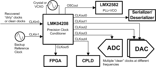
LMK04208 simplified_schematic_snas684.gif

4 改訂履歴

日付 改訂内容
2016年9月 * 初版