SBAA293C June 2018 – March 2023 AMC1035 , AMC1035-Q1 , AMC1200-Q1 , AMC1204-Q1 , AMC1211-Q1 , AMC1300B-Q1 , AMC1301-Q1 , AMC1302-Q1 , AMC1304L05-Q1 , AMC1304L25-Q1 , AMC1304M05-Q1 , AMC1304M25-Q1 , AMC1305L25-Q1 , AMC1305M05-Q1 , AMC1305M25-Q1 , AMC1336-Q1 , AMC3301-Q1 , AMC3302-Q1 , AMC3330-Q1 , AMC3336-Q1
Introduction
The global market for electric vehicles (EVs) and hybrid electric vehicles (HEVs) is rapidly growing as these vehicles offer higher fuel-efficiency and lower emissions compared to gasoline or diesel vehicles and use power from renewable energy sources. To control energy flow and optimize efficiency in HEV/EV powertrain subsystems such as traction inverters, on-board chargers (OBCs), DC/DC converters, and battery management systems (BMS), precise and accurate current measurement is essential. These high-voltage subsystems must measure large currents at high voltages, typically >400 V. Thus, these current measurements require isolation as well as high performance in harsh automotive environments.
Different Isolated Current Measurement Methods
Each HEV/EV application has different cost, accuracy, signal bandwidth, latency, measurement range, isolation ratings, and package size requirements. There are several isolated current measurements methods. However, the primary methods used in HEV/EV subsystems are either shunt-based using isolated amplifiers (Figure 1) or isolated modulators (Figure 2) or hall-based using open-loop (Figure 3) or closed-loop (Figure 4) hall sensors.
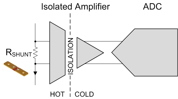 Figure 1 Isolated
Amplifier
 |
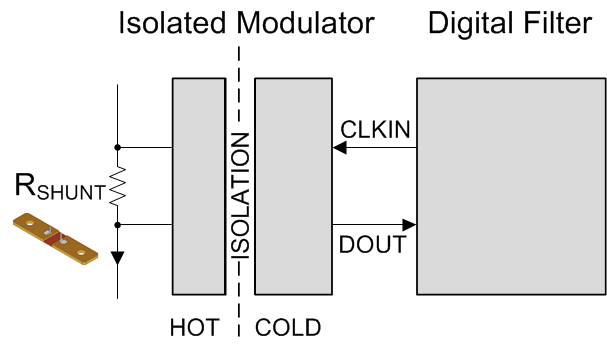 Figure 2 Isolated
Modulator
 |
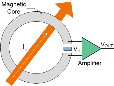 Figure 3 Open-Loop
Hall Sensor
 |
 Figure 4 Closed-Loop
Hall Sensor
 |
Comparison of Shunt- and Hall-Based Methods
Historically, designers preferred shunt-based solutions for low-current (<50 A), and hall-based solutions for high-current (>50 A) measurements. However, because of the increasing current measurement accuracy requirements, automotive suppliers are migrating from hall-based to shunt-based methods, especially in high-current environments. There is even a trend amongst automotive suppliers to move from isolated amplifier based solutions to isolated modulator based solutions to further improve measurement accuracy.
Texas Instruments offers best-in-class isolated amplifiers and isolated modulators that help achieve very accurate isolated current measurements over temperature when paired with high-precision shunts. Table 1 shows the basic differences between shunt- and hall-based isolated current-sensing solutions in high-current automotive environments.
| CATEGORY | SHUNT-BASED | HALL-BASED |
|---|---|---|
| Solution size | Similar | Similar |
| offset | Very low | Medium |
| Offset drift over temperature | Low | Medium |
| Accuracy | <0.5% after calibration | <2% after calibration |
| Noise | Very low | High |
| Bandwidth | Similar | Similar |
| Latency | Similar | Similar |
| Nonlinearity | Very low | High |
| Long-term stability | Very high | Medium |
| Cost | Similar | Similar |
| Vibration impact | Very low | Low |
| Power dissipation | Low | Very low |
| Customization | Flexible | Limited |
Analysis of Shunt- and Hall-Based Methods
- Hall-sensors are inherently isolated, which allows a single-module approach. On the other hand, shunt-based solutions require an isolated amplifier or modulator, and an isolated power-supply for the high common-mode voltage side.
- Shunt-based solutions have very low initial offset, have lower offset drift over temperature, and are less susceptible to external magnetic fields.
- Shunt-based solutions are linear over the entire voltage range compared to hall-based solutions that are nonlinear, especially at zero crossing and near the magnetic core saturation region.
- Shunt-based solutions achieve better DC accuracy over temperature compared to hall-based solutions with basic one-time calibration. The accuracy of shunt-based solutions is much better particularly at low currents because of limited sensitivity to external magnetic fields.
- The voltage drop across the inline shunt results in thermal dissipation and power loss. However, with improvements in shunt technology, the shunts have become lighter, the ohmic values have decreased, and the accuracy and drift performance have improved. The use of low-value ohmic shunts results in less thermal dissipation. Additionally, Texas Instruments' isolated amplifiers and modulators support very small input voltage ranges (±50 mV and ±250 mV) with a superior overall accuracy. These improvements in shunt technology and the availability of small input range isolated devices allow systems to have less thermal dissipation without compromising the overall measurement accuracy.
- Hall-based sensors generally have a limited operating temperature range (typically from –40°C to +85°C), whereas shunt-based solutions can support higher operating temperature ranges (typically from –40°C to +125°C).
- Both hall-based and shunt-based isolated amplifier solutions offer similar signal bandwidth, typically up to a few hundred kilohertz (kHz). However, isolated modulators provide a high-speed bit-stream output that allows the user to implement and customize digital filtering externally. This customization allows the user to develop high-signal bandwidth and low-latency solutions.
Isolated Shunt-Based Current Sensing in Traction Inverters
A traction inverter controls the electric motor and is a key component in the HEV/EV drivetrain. A traction inverter requires accurate current sensing at high common-mode voltages. Current measurements in traction inverters can therefore be realized using one of two shunt-based methods.
Figure 5 shows the voltage drop across the shunt on the hot (high common-mode voltage) side is isolated from the cold side with an automotive grade, reinforced isolated amplifier such as the AMC1301-Q1.
Figure 6 shows the second shunt-based measurement method that uses an automotive-grade, reinforced isolated modulator such as the AMC1305M25-Q1 to isolate the voltage drop across the shunt on the hot side from the cold side.
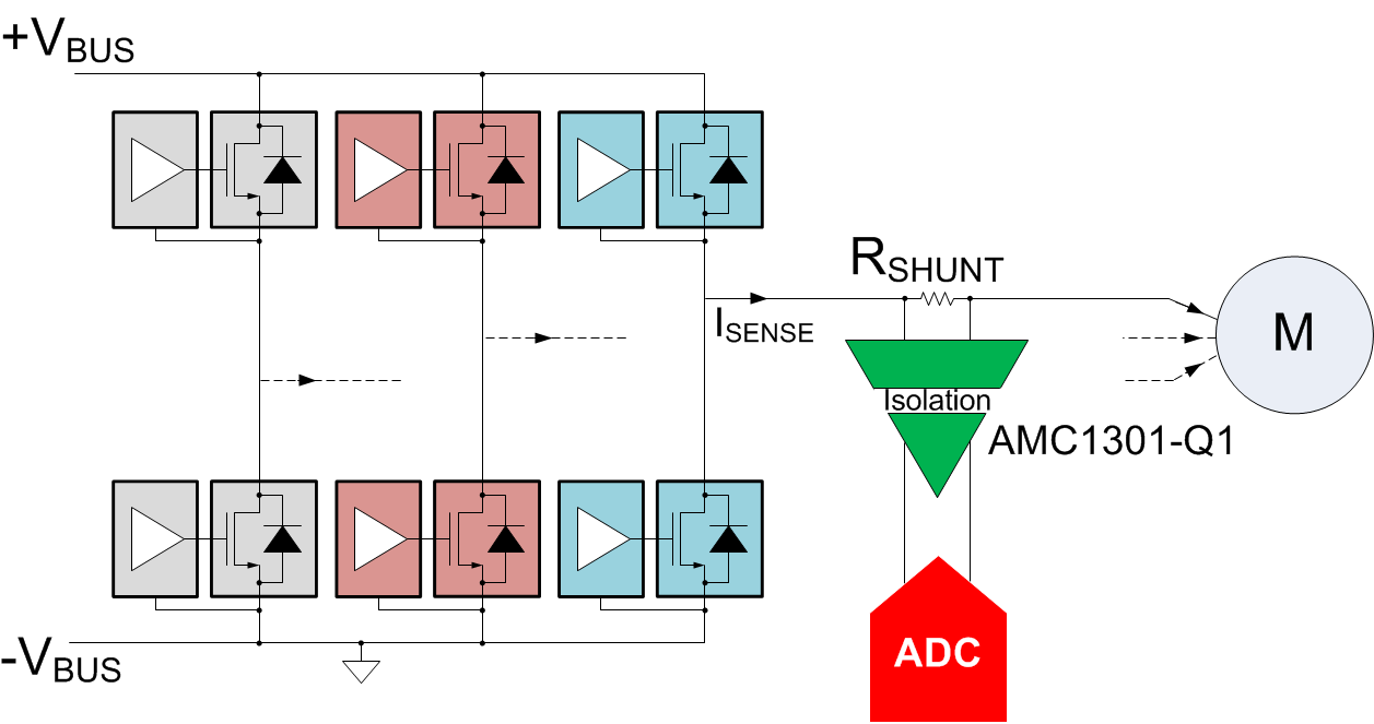 Figure 5 Isolated
Current Measurement Using Isolated Amplifiers
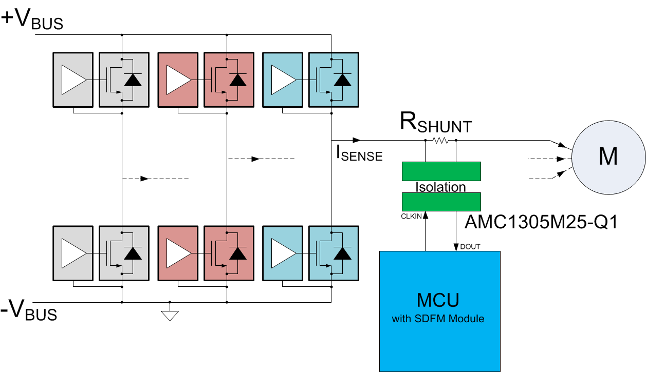 Figure 6 Isolated
Current Measurement Using Isolated Modulators
Figure 6 Isolated
Current Measurement Using Isolated ModulatorsFor improved measurement accuracy, use an isolated modulator because this solution eliminates an additional analog-to-digital conversion stage and the associated subsequent errors. The high-speed bit-stream output from the isolated modulators is filtered by microcontrollers (MCUs) such as TI's C2000 family that have a built-in sigma-delta filter module (SDFM) or by an FPGA, allowing the user to fine-tune signal bandwidth and accuracy.
Automotive Isolated Device Recommendations
| DEVICE | ISOLATION | DESCRIPTION |
|---|---|---|
| AMC1305-Q1 | Reinforced | ±50-mV, ±250-mV isolated modulator |
| AMC1301-Q1 | Reinforced | ±250-mV isolated amplifier |
| AMC1302-Q1 | Reinforced | ±50-mV isolated amplifier |
Conclusion
Multiple measurement methods exist for isolated current sensing in HEV/EV subsystems including shunt-based and hall-based methods. With advancements in affordable high-precision shunts and high-performance isolated amplifiers and modulators, shunt-based solutions have become good alternatives to traditional hall-based solutions.