SBAU396 May 2022
3.1 Power Circuitry
Most precision ADC EVMs are powered directly from the USB-powered PA007 precision host adapter (PHI) controller board. The PA007 board outputs 5.5 V, which is commonly used for the analog supplies, and either 3.3 V or 1.8 V for digital, I/O, and EEPROM supplies. To match the supply voltages, the ADC-PHI-PRU-EVM converts and routes the 5-V, 3.3-V, and 1.8-V supplies that are featured on the HSE connector to the QSH connector.
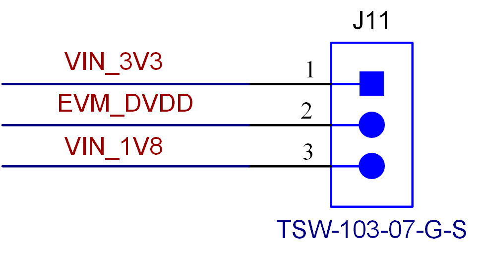
As shown in Figure 3-1, J11 selects the DVDD voltage routed to the QSH connector between the 3.3-V and 1.8-V supplies from the AM64x and AM24x HSE connector.
 Figure 3-1 J11 Selects Between the 3.3-V and 1.8-V DVDD
Supplies for the ADC
Figure 3-1 J11 Selects Between the 3.3-V and 1.8-V DVDD
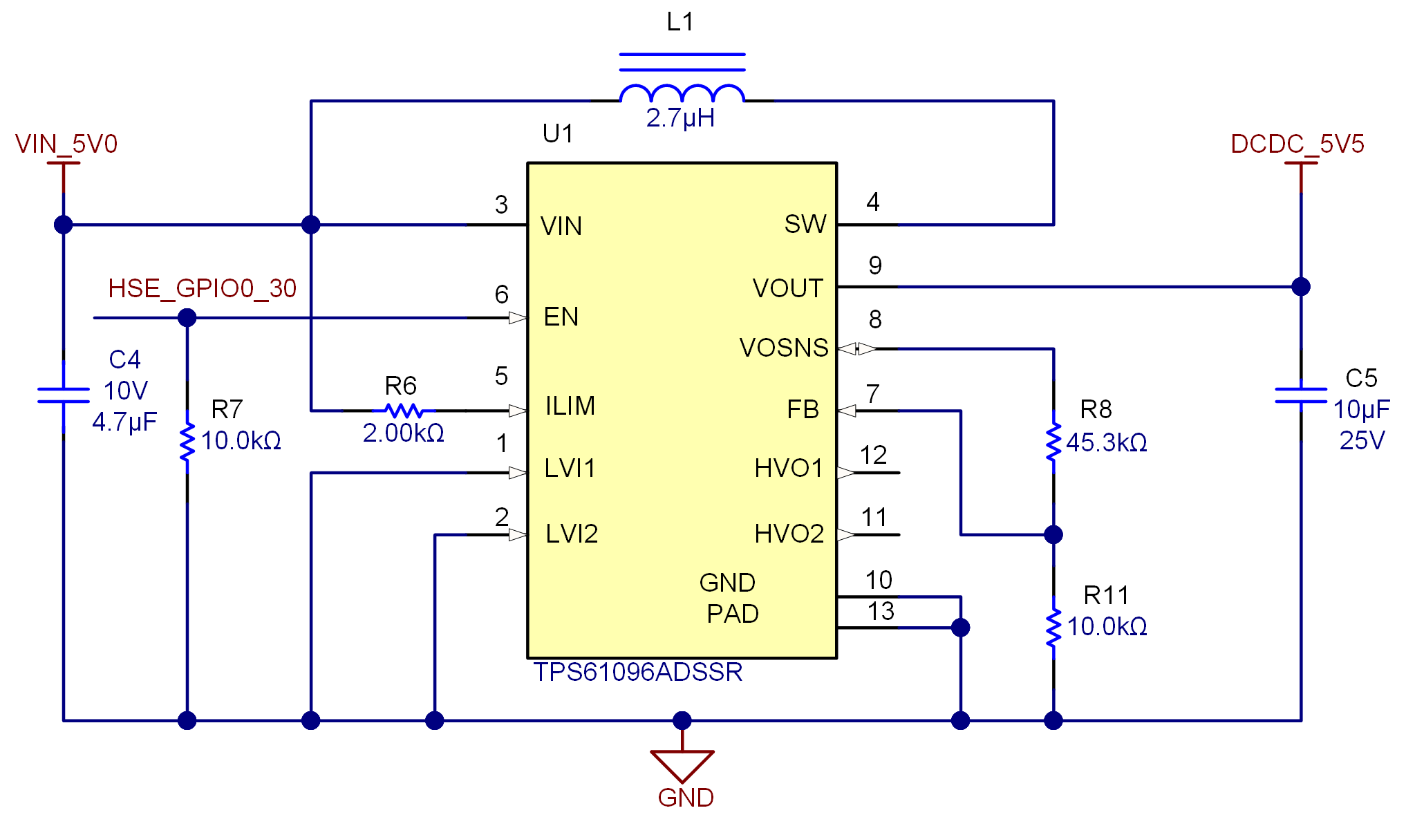
Supplies for the ADCFigure 3-2 shows that a TPS61096 boost converter on the ADC-PHI-PRU-EVM converts the 5.0-V HSE output to the 5.5-V output to match the typical output of the PA007 motherboard. The feedback network formed from R8 and R11 sets the output voltage to approximately 5.5 V.
 Figure 3-2 TPS61096 Boost Converter Circuitry
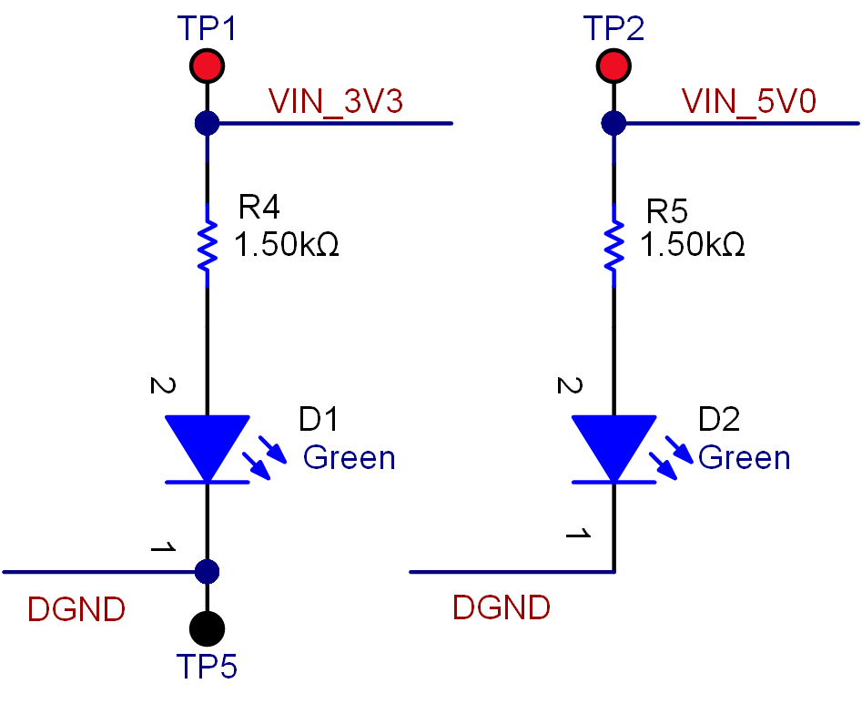
Figure 3-3 shows the D1 and D2 indicator LEDs that confirm the presence of the 5-V and 3.3-V supplies from the AM64x and AM24x EVM (TMDS64GPEVM and TMDS243GPEVM) HSE connectors.
 Figure 3-3 D1 and D2 LEDS