SBAU419 November 2022 TMAG5170
2.4 Rotation
Rotation is a useful function whenever motors are involved. Magnets mounted to a spinning motor shaft may be used to track absolute angle or track incremental step-wise rotation. Incremental rotation relies on counting state transitions to track the motor position, and therefore does not offer the same resolution from angle measurements. Incremental rotary position is appropriate when speed, direction, and revolutions are being measured. Angle measurements are important when precise position control is required.
More information about these functions can be found in Reducing Quadrature Error for Incremental Rotatry Encoding Using 2D Hall-effect Sensors and TIDA-060040
During a rotation simulation, the magnet will rotate about the Z-axis. The only required input is "Arc Length" in the Magnet Motion section. Typically this will be 360 for a full rotation, but may be set higher or lower to generate data for any region of interest.
"Z Angle" can be adjusted to define the rotation starting angle. Normally, "X Position" and "Y Position" should be set to 0. Any offset for either of these values produces run-out, which is when the axis of rotation is not aligned to the center of the object. Similarly, adding tilt to the magnet alignment in "X Angle" or "Y Angle" simulates wobble, which occurs when the magnet is not orthogonal to the rotating axis.
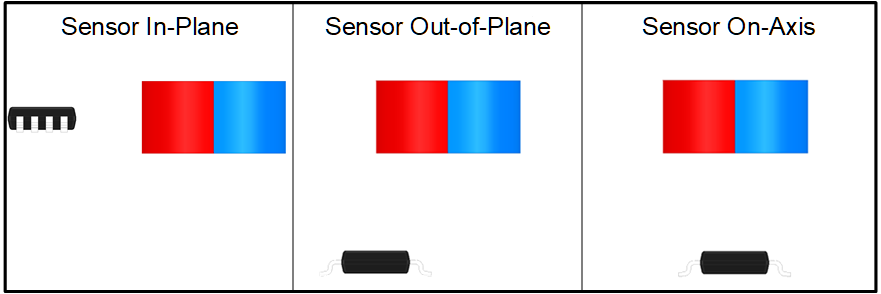
Depending on the mechanical constraints and how the magnet is to be observed, sensors can be placed on the axis of rotation (On-Axis), coplanar to the magnet center (In-Plane), or anywhere else a strong enough field may be measured in the axes of interest (Off-Axis).
 Figure 2-16 Sensor-Magnet Alignments
The user prompt for rotation simulation appears as in #GUID-0EC4F4E0-A925-4165-B8E6-7E9A7779F47C.