SBAU419 November 2022 TMAG5170
4.1.4 Latch
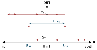
A latch type device operates similarly to a unipolar switch with thresholds at BOP and BRP. The key difference is that BHYS is set such that BRP = -BOP. For this case, the sensor requires an alternating input field for the device to be able to switch between output states. This is particularly useful for cases that use rotating magnets such as in incremental angle encoders or when the magnet may travel past the sensor in two directions, such as might occur in a toggle switch.
 Figure 4-6 Latch Output
Configuring a latch device similarly allows radio buttons for selecting threshold limits based on published data sheet parameters. It is likewise recommended to check mechanical design against BOP Max and BRP Min to ensure all devices observe conditions sufficient to achieve the desired output response.
Latch user inputs appear similar to the inputs required for a switch device.