SBOA166D October 2016 – August 2022 INA240 , INA240-Q1 , INA253 , INA253-Q1 , INA254 , INA281 , INA281-Q1 , INA293 , INA293-Q1
TI Tech Note
A solenoid is an electromechanical device that is made up of a coil wound around a movable iron material, also called an armature or plunger. When an electric current is passed through the coil, a magnetic field is generated, causing the armature to travel over a fixed range. Figure 1-1 shows an illustration of an electromechanical solenoid. Solenoids are often designed for simple ON - OFF applications like relays that require only two states of operation. These solenoids can be also be designed for linear operation where the current is proportional to the position of the armature. Linear solenoids are used in several applications where pressure, fluid, or air is precisely regulated. In automotive applications, linear solenoids are used in fuel injectors, transmission, hydraulic suspension, and for haptic effects. Linear solenoids are seen in critical medical applications that require precise air flow control as well as industrial applications that redirect and control fluid flow.
 Figure 1-1 Electromechanical Solenoid
Construction
Figure 1-1 Electromechanical Solenoid
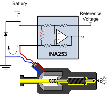
ConstructionThere are multiple configurations for connecting and driving solenoids. One common approach to driving solenoids is to use a high-side driver configuration. In this configuration, the current sense amplifier is connected between high-side switch and the solenoid as shown in Figure 1-2. One benefit to this configuration is the solenoid is isolated from the battery voltage when the high-side switch is turned off. Eliminating the continuous connection of the solenoid to the battery voltage reduces solenoid degradation and early lifetime failures making the system safer and more reliable.
 Figure 1-2 High-Side Drive With High-Side
Current Sense
Figure 1-2 High-Side Drive With High-Side
Current SenseThe current sense amplifier shown in Figure 1-2 must be able to reject high common-mode dv/dt signals as well as support common-mode voltages that fall below ground. In the above configuration when the high-side switch is turned on, the solenoid is energized by the current flowing from the battery. The duty cycle of the high-side switch determines the current flowing through the solenoid, which in turn controls the travel range of the plunger. At the time when the high-side switch is turned off, the current flows through the flyback diode forcing the common voltage to drop one diode drop below ground.
Solenoids and valves are highly inductive in nature. The effective impedance of the solenoid can be simplified as resistance and inductance. The coil is constructed using copper (4000ppm/°C) and the effective resistance varies on the type of solenoids from 1 Ω for haptic applications to 10 Ω for a linear or positional valve systems. The inductance for all of the solenoids ranges from 1 mH to 10 mH. Figure 1-3 shows an example of the current profile of a solenoid driver in open-loop mode at 25°C and 125°C. Over a 100°C rise in ambient temperature without compensating for Cu resistance, the plunger travel distance accuracy is around 40%. The solenoid current flow directly controls the plunger's travel distance. If the ambient temperature changes, the plunger's travel distance changes impacting the output control which could be regulating pressure, fluid, or air.
 Figure 1-3 Solenoid Current Profile
Across Temperature
Figure 1-3 Solenoid Current Profile
Across TemperatureMeasuring current in solenoid and valve applications provides the capability to detect changes in the operating characteristics of a solenoid. Current measurement can identify the effects of a decrease in the magnetic field of an aging solenoid to detect faulty components before they fail. In an open-loop solenoid control system, the variation of effective impedance can drift 40% for a 100°C rise in temperature from the copper windings. Current measurement used in a current control feedback loop can reduce the solenoid's impedance variation over temperature from 40% down to 0.2% using the INA253 current sense amplifier making the system more efficient, more reliable, and safer.
The INA253 is a high-side, bidirectional current sense amplifier with an integrated 2-mΩ low inductive shunt that can support large common-mode voltages ranging from –4 V to +80 V. The integrated shunt is factory calibrated to provide < 0.1% total system accuracy with a gain error temperature drift of < 15 ppm/°C. The INA253 is specifically designed to operate within PWM applications where high dv/dt transients need to be suppressed. INA253 is designed with circuitry to suppress dv/dt signals. This features lowers blanking time enabling accurate PWM current measurements at lower duty cycle. The device's low offset voltage, drift, gain, and high bandwidth of 400 kHz enables accurate in-line current measurements for PWM applications. Valve applications requiring precision control of fluid, air, and pressure all benefit from the accuracy and temperature stability in the current measurement by using the INA253. The integrated precision shunt of the INA253 can provide a high-accuracy position control of <0.2% across temperature, eliminating the need for current measurement calibration across temperature.
Alternate Device Recommendations
The INA241 is the ultra-precise analog current-sense amplifier. The INA241 can be used in high-voltage bidirectional applications paired with 1-MHz bandwidth, low offset voltage of 12 µV (maximum), drift of 250nV/°C (maximum), and gain of 0.05% to offer fast response time with precise control for in-line control within solenoid applications. The INA241 can measure currents at common-mode voltages of –5 V to 110 V and can survive voltages between –20V to 120V.
The INA293 is another device to recommend for this application. The INA293 is a unidirectional current sense amplifier that can support a common-mode voltage from –4 V to 110 V and can survive –20 V to 120 V. This large negative common-mode survivability is important due to inductive kickbacks seen when engaging the solenoid. The INA293 also has a high-bandwidth of 1 MHz which enables fast response times in the event of an overcurrent scenario. Furthermore, the INA293 is an high-precision current sense amplifier with a low offset voltage of 15 µV and gain error of 0.15%.
The INA281 unidirectional current sense amplifier is another recommended device. The INA28a supports a common-mode voltage from –4 V to 110 V and can also survive –20 V to 120 V. The INA281 has a high bandwidth of 1 MHz for fast response time in-line measurements.
| DEVICE | OPTIMIZED PARAMETER | PERFORMANCE TRADE-OFF |
|---|---|---|
| INA241 | Vcm : –5 V to
110 V, Bidirectional, Bandwidth: 1 MHz, Vos: 12 µV |
Higher IQ |
| INA293 | Vcm : –4 V to
110 V, Bandwidth: 1.3 MHz, Vos: 15 µV |
No enhanced PWM rejection |
| INA281 | Vcm range: –4
V to 110 V, Bandwidth: 1.3 MHz |
No enhanced PWM
rejected, Offset voltage: 50 µV |
| DOCUMENT | TITLE |
|---|---|
| SBOA189 | Precision Brightness and Color Mixing in LED Lighting Using Discrete Current Sense Amplifiers |
| SBOA161 | Low-Drift, Low-Side Current Measurements for Three-Phase Systems |
| SBOA163 | High-Side Motor Current Monitoring for Over-Current Protection |
| SBOA193 | Safety and Protection for Discrete Digital Outputs in a PLC System Using Current Sense Amplifiers |