SBOA426 March 2021 INA233
2 Group Command Details
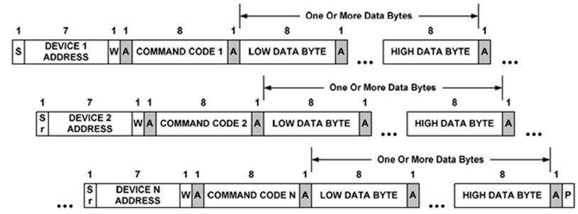
INA233 supports group protocol as defined in the PMBus specification. The group command allows the host processor to easily communicate with multiple devices on the bus. Commands are sent in one continuous transmission, and the STOP condition at the end serves as the “go” command. Upon detection of the STOP condition, all devices begin executing the received command. During the transmission, each device can receive only one command, and the commands don’t have to be identical for all devices.
The INA233 also supports packet error checking (PEC). PEC is an optional feature which can help improve communication robustness. In this study, communication protocol was implemented without PEC.
The format of group protocol is shown in Figure 2-1. In this study, the one-shot (or triggered) conversion command is transmitted to each of the INA233 serially by writing to the MFR_ADC_CONFIG register. Repeated START conditions are used to separate the devices from each other.
 Figure 2-1 PMBus Group Command Protocol without
PEC
Figure 2-1 PMBus Group Command Protocol without
PECFor each device, the command is identical in format to a normal write word, except no STOP condition is generated unless the last device has been addressed and the end of the transmission has been reached. Figure 2-2 shows the write word command. The STOP condition (highlighted) at the end should be omitted unless the transmission is targeting the very last device in the group.
As we can see from Figure 2-2, four bytes of data are sent to each member within the group. The first byte is the unique device address; the second byte is the command code. In this study, the command code is D0h, or register MFR_ADC_CONFIG. It is followed by two bytes of data with mode bits (bit2 to bit0) set to “001”. This instructs the INA233 to start converting shunt voltage in triggered mode upon receiving the command.
 Figure 2-2 INA233 Write Word
Results are presented in this application report for the INA233, but the PMBus group command functionality is applicable to other TI devices that support PMBus.