SBOA514A March 2021 – August 2021 DRV5032 , TMAG5170 , TMAG5231 , TMAG5273
3 Case tamper detection
Case tamper detection
Certain applications implement secure enclosures or casings that are meant to be inaccessible by others. Example applications include electricity meters, gas meters, electronic point of sale (EPOS), set-top boxes (STB), ATMs, and enterprise servers. Often, intrusion attempts such as opening the enclosure or casing must be detected for these types of applications.
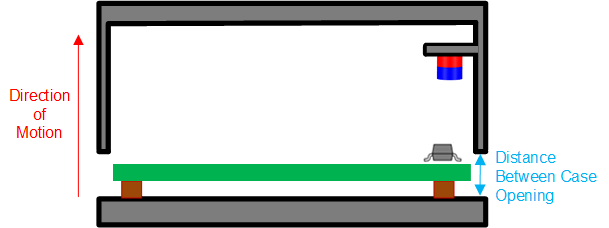
One method of implementing this case tamper detection feature is by placing a cylinder magnet on the case and placing a Hall switch directly underneath the magnet, as Figure 3-1 shows. When the case is closed, the Hall position sensor senses that the magnetic flux density is beyond the BOP of the Hall switch. As the case is opened, the magnet will move with the case so that it is further away from the Hall sensor.
 Figure 3-1 Case Tamper Detection
Implementation
Figure 3-1 Case Tamper Detection
ImplementationAs the distance from the magnet and sensor increases, the sensed magnetic flux density decreases. Eventually, the magnet-to-sensor distance would reach a distance threshold that causes the sensed magnetic flux density to fall below the magnetic flux density limit, which would trigger the output state of the Hall position sensor to change and alert the system of the case opening. For this type of detection scheme, the magnetic flux density limit value is set by the BRP specification of the Hall switch. The Hall position sensor should be selected so that its BRP would equal the resulting magnetic flux density when the magnet-to-sensor distance is at the desired distance threshold. There is also some consideration that needs to be made to ensure that the magnetic flux density when the case is closed is far enough away from the magnetic flux density limit to prevent false trips.
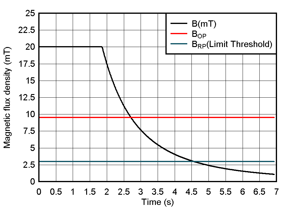
Figure 3-2 shows the relationship between BOP, BRP, and the limit threshold for detecting the opening of the case. In this figure, the sensed magnetic flux density is constant until the case is opened.
 Figure 3-2 Magnetic Flux Density for Case
Tamper Detection