SCDA044 January 2023 TMUX1308
1.4 Using Multiple Devices to Create Desired Multiplexer Configuration
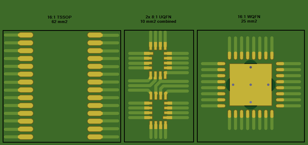
With increasingly smaller package sizes being offered, more options exist to replace higher pin count devices with multiple lower pin count devices to achieve the same multiplexer configuration. Smaller package sizes also allow designers to build their desired configuration using multiple devices without sacrificing board space. For example, using two UQFN 8:1 devices instead of a single TSSOP or WQFN 16:1 saves on board space since the RSV package (UQFN) is 10 mm2 when combined versus the PW (TSSOP) is 62 mm2 and the RTV (WQFN) is 25 mm2. The drain pin on each UQFN device need to be connected together and the digital logic pins can share I/O controls from the MCU. The enable pins are then used to select which device and switch path will be connected. This configuration can be shown in Figure 1-6.
 Figure 1-6 PCB Space Savings Using Two
8:1 Devices Instead of One 16:1 Device