SCDU025 May 2021
5 EVM Setup
The following instructions are for setting up the EVM:
If you desire to use this EVM with all channels loaded, then solder down your chosen 0805 components to the channels you wish to test. Table 5-1 describes which loads correspond to what pin on the TMUX646.
Table 5-1 Configurable Load MatrixPin Name 0805 Resistor Pad ID (SE) 0805 Capacitor Pad ID (D) 0805 Resistor Pad ID (D) D1P R12 C4 R10 D1N R11 C4 R10 D2P R9 C3 R7 D2N R8 C3 R7 D3P R6 C2 R4 D3N R5 C2 R4 D4P R3 C1 R1 D4N R2 C1 R1 CLKP R14 C5 R13 CLKN R15 C5 R13 DA1P R21 C7 R19 DA1N R20 C7 R19 DA2P R24 C8 R22 DA2N R23 C8 R22 DA3P R27 C9 R25 DA3N R26 C9 R25 DA4P R30 C10 R28 DA4N R29 C10 R28 CLKAP R17 C6 R16 CLKAN R18 C6 R16 DB1P R36 C12 R34 DB1N R35 C12 R34 DB2P R39 C13 R37 DB2N R38 C13 R37 DB3P R42 C14 R40 DB3N R41 C14 R40 DB4P R45 C15 R43 DB4N R44 C15 R43 CLKBP R33 C11 R31 CLKBN R32 C11 R31 - Power the board by
attaching a 1.65 V – 5.5 V power supply, current limited to 25 mA, with the
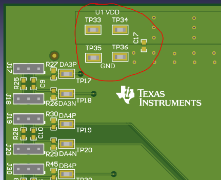
positive terminal attached to TP33 or TP34 at the top right of the board under
the label U1 VDD. Attached the negative terminal to TP35 or TP36 at the
top right of the board above the label GND. The TMUX646 is now powered.
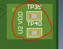
To power U2, attach the positive power terminal to TP39 or TP40. Figure 5-1 below shows the test points circled in
red.

 Figure 5-1 TMUX646EVM Power
Connections for U1 and U2.. TMUX646EVM Power Connections for U1 and U2. Both IC pads share the
same ground connection
 -
This EVM comes with shunts to connect the jumpers – The jumpers have three pins and are set up in the following way.
Table 5-2 3-Pin Header: Signal to Pin MatrixPosition 1 Position 2 Position 3 GND Floating VDD With the EVM in the same orientation (as shown in Figure 4-1), the jumpers and their positions are oriented according to Table 5-3. All headers have their respective 2nd pin in the center with a pin above and pin below. This is the second position of the header.
Table 5-3 Jumper ID to EVM Orientation MatrixJumper ID IC ID Position 1 – (GND) Position 3 – (VDD) J1 – J16 U1 LEFT RIGHT J17 – J30 U1 RIGHT LEFT J31, J32 U1 RIGHT LEFT J33, J34 U2 BOTTOM TOP -
Next, please refer to Table 5-4 below to prepare the EN and SEL pins to configure the channels.
Table 5-4 TMUX646EVM: Truth TableEN SEL Channels Selected 1 x Device Disabled 0 0 xP; xN <-> xAP; xAN Connected xP; xN <-> xBP; xBN Disconnected 0 1 xP; xN <-> xBP; xBN Connected xP; xN <-> xAP; xAN Disconnected Please see Table 5-5 for jumper configurations on the SEL and EN pin.
Table 5-5 TMUX646EVM Board Configuration – Control SignalsJumper ID Test Point ID IC – Pin Shunt Position 1 Shunt Position 2 Board Function J31 TP31 U1 – /OE 1 2 U1 Enabled 3 2 U1 Disabled N/A N/A Floating; Attach External Enable Source J33 TP41 U2 – /OE 1 2 U2 Enabled 3 2 U2 Disabled N/A N/A Floating; Attach External Enable Source J32 TP32 U1 – SEL 1 2 U1 – A Channel Connected 3 2 U1 – B Channel Connected N/A N/A Floating; Attach External Select Source J34 TP42 U2 – SEL 1 2 U2 – A Channel Connected 3 2 U2 – B Channel Connected N/A N/A Floating; Attach External Select Source The TMUX646 has 1.8 V compatible logic thresholds, where digital signal levels are compatible for a 1.8 V system, independent of supply voltage. Refer to Table 5-6 below for defined logic levels.
Table 5-6 TMUX646EVM: Logic LevelsParameter Min Max Input High Voltage 1.4 V 5.5 V Input Low Voltage 0 V 0.5 V -
Next, configure the multiplexer’s channels based on Table 5-7.
Table 5-7 TMUX646EVM Board Configuration – I/O SignalsJumper ID TP ID IC – Pin Shunt Position 1 Shunt Position 2 Board Function J1 TP1 U1 – D4P 3 2 IC Pin = VDD 2 1 IC Pin = GND N/A N/A IC Pin = Float J2 TP2 U1 – D4N 3 2 IC Pin = VDD 2 1 IC Pin = GND N/A N/A IC Pin = Float J3 TP3 U1 – D3P 3 2 IC Pin = VDD 2 1 IC Pin = GND N/A N/A IC Pin = Float J4 TP4 U1 – D3N 3 2 IC Pin = VDD 2 1 IC Pin = GND N/A N/A IC Pin = Float J5 TP5 U1 – D2P 3 2 IC Pin = VDD 2 1 IC Pin = GND N/A N/A IC Pin = Float J6 TP6 U1 – D2N 3 2 IC Pin = VDD 2 1 IC Pin = GND N/A N/A IC Pin = Float J7 TP7 U1 – D1P 3 2 IC Pin = VDD 2 1 IC Pin = GND N/A N/A IC Pin = Float J8 TP8 U1 – D1N 3 2 IC Pin = VDD 2 1 IC Pin = GND N/A N/A IC Pin = Float J9 TP9 U1 – CLKP 3 2 IC Pin = VDD 2 1 IC Pin = GND N/A N/A IC Pin = Float J10 TP10 U1 – CLKN 3 2 IC Pin = VDD 2 1 IC Pin = GND N/A N/A IC Pin = Float J11 TP11 U1 – CLKAP 3 2 IC Pin = VDD 2 1 IC Pin = GND N/A N/A IC Pin = Float J12 TP12 U1 – CLKAN 3 2 IC Pin = VDD 2 1 IC Pin = GND N/A N/A IC Pin = Float J13 TP13 U1 – DA1P 3 2 IC Pin = VDD 2 1 IC Pin = GND N/A N/A IC Pin = Float J14 TP14 U1 – DA1N 3 2 IC Pin = VDD 2 1 IC Pin = GND N/A N/A IC Pin = Float J15 TP15 U1 – DA2P 3 2 IC Pin = VDD 2 1 IC Pin = GND N/A N/A IC Pin = Float J16 TP16 U1 – DA2N 3 2 IC Pin = VDD 2 1 IC Pin = GND N/A N/A IC Pin = Float J17 TP17 U1 – DA3P 3 2 IC Pin = VDD 2 1 IC Pin = GND N/A N/A IC Pin = Float J18 TP18 U1 – DA3N 3 2 IC Pin = VDD 2 1 IC Pin = GND N/A N/A IC Pin = Float J19 TP19 U1 – DA4P 3 2 IC Pin = VDD 2 1 IC Pin = GND N/A N/A IC Pin = Float J20 TP20 U1 – DA4N 3 2 IC Pin = VDD 2 1 IC Pin = GND N/A N/A IC Pin = Float J21 TP21 U1 – CLKBP 3 2 IC Pin = VDD 2 1 IC Pin = GND N/A N/A IC Pin = Float J22 TP22 U1 – CLKBN 3 2 IC Pin = VDD 2 1 IC Pin = GND N/A N/A IC Pin = Float J23 TP23 U1 – DB1N 3 2 IC Pin = VDD 2 1 IC Pin = GND N/A N/A IC Pin = Float J24 TP24 U1 – DB1P 3 2 IC Pin = VDD 2 1 IC Pin = GND N/A N/A IC Pin = Float J25 TP25 U1 – DB2N 3 2 IC Pin = VDD 2 1 IC Pin = GND N/A N/A IC Pin = Float J26 TP26 U1 – DB2P 3 2 IC Pin = VDD 2 1 IC Pin = GND N/A N/A IC Pin = Float J27 TP27 U1 – DB3N 3 2 IC Pin = VDD 2 1 IC Pin = GND N/A N/A IC Pin = Float J28 TP28 U1 – DB3P 3 2 IC Pin = VDD 2 1 IC Pin = GND N/A N/A IC Pin = Float J29 TP29 U1 – DB4N 3 2 IC Pin = VDD 2 1 IC Pin = GND N/A N/A IC Pin = Float J30 TP30 U1 – DB4P 3 2 IC Pin = VDD 2 1 IC Pin = GND N/A N/A IC Pin = Float J35 N/A (SMA) U2 – CLKP N/A N/A N/A (SMA) J36 N/A (SMA) U2 – CLKN N/A N/A N/A (SMA) J37 N/A (SMA) U2 – CLKAP N/A N/A N/A (SMA) J38 N/A (SMA) U2 – CLKAN N/A N/A N/A (SMA) J39 N/A (SMA) U2 – CLKBP N/A N/A N/A (SMA) J40 N/A (SMA) U2 – CLKBN N/A N/A N/A (SMA)