SCPU047 December 2022 TCA39416
5 Enabling Bus Capacitance
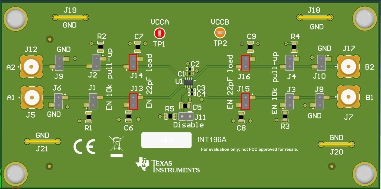
Bus capacitance can be enabled by placing a jumper on J13, J14, J15, and J16. Bus capacitance values are 22 pF with 5% tolerance. The A2, A1, B2, and B1 traces are set to be 50 Ω characteristic impedance and the expected parasitic capacitance from the trace is about 6 pF. TCA39416 A/B pins are a typical bus capacitance of 4 pF and a max of 8 pF. This means without the bus cap enabled, the load is a maximum of 14 pF. With the bus capacitance selector enabled, the bus capacitance is about 36 pF. The controller or target connected to this board increases the capacitance further. Recall the I3C max bus capacitance Ver 1.1.1 is 50 pF and this device does not redrive or separate the capacitive loading. This means enabling both sides violates the max loading allowed by I3C standard.
 Figure 5-1 Capacitance Enable