SLAA486B January 2011 – June 2019 MSP430G2452
3 Software
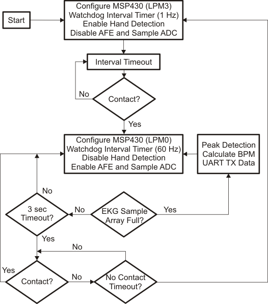
Figure 3 shows the flow chart for this application software.
 Figure 3. Software Flowchart
 It begins by initializing the MSP430 in LPM3 sleep mode, configuring the watchdog timer in interval-timer mode (sourced by ACLK or VLO), and disabling the AFE. When the interval (approximately 1 second) expires, the ADC is triggered for single-channel single conversion. With the hand-detection circuit enabled, the left pad is sampled by the ADC and compared against a set of thresholds to determine the quality of contact. If the voltage on the left pad exceeds 1.7 V, the contact is considered good, and the green LED on the LaunchPad kit flashes briefly. If the voltage exceeds 1.5 V, the contact is considered bad and the red LED flashes briefly. The default value on the pad for no contact is 0.825 V (with 3.3-V supply voltage).
If there is no contact, the MSP430 MCU enters LPM3 sleep mode until the interval expires again. If there is contact (good or bad), the hand-detection circuit is disabled, the AFE is enabled, the watchdog interval timer is sourced from MCLK/DCO, and the sleep mode changed to LPM0. The DCO runs with a calibrated value of 1 MHz, and the interval timer runs at 60 Hz. Therefore, the ADC is triggered to sample the amplified and filtered EKG signal at the output of the AFE every 16 milliseconds. The digital conversion values are stored in memory and are used by the heart rate detection algorithm to compute the number of heartbeats per minute [9].
The heart rate value is transmitted using a Timer_A based UART. The UART output can be relayed to the PC by means of either the back-channel UART-over-USB connection on the LaunchPad kit or the eZ430 RF target header on the daughterboard. During the EKG sampling by the ADC, the hand-detection circuit is momentarily enabled every 3 seconds to ensure that contact is being made. If there is contact, the application returns to EKG sampling. If not, the hand-detection circuit remains enabled, and the applications checks for contact for approximately 10 seconds. If there is still no contact, the AFE is disabled and the MSP430 MCU returns back to the initial LPM3 state in which it checks for contact every second.
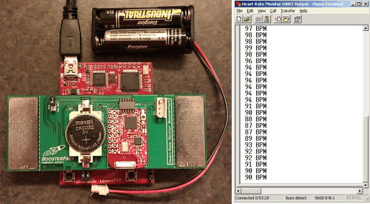
Details on programming the software on the heart-rate monitor setup are provided in Section B and the eZ430 RF target boards in Section C. Figure 4 shows the complete hardware in action (left side) and the UART output log display on the HyperTerminal application window on the PC (right side).
 Figure 4. Heart-Rate Monitor Setup (left) and UART Output on PC (right)